


6
2
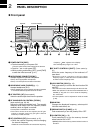
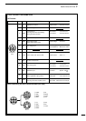
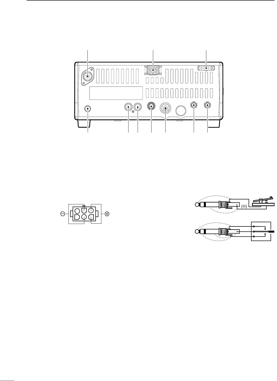
PANEL DESCRIPTION
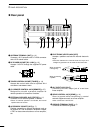
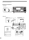
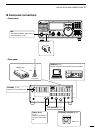
n Rear panel
q ANTENNA TERMINAL [ANT] (p. 10)
Connects a 50
Ω antenna with a PL-259 connector
and a 50 Ω coaxial cable.
w DC POWER SOCKET [DC 13.8V] (p. 12)
Accepts 13.8V DC through the supplied DC power
cable.
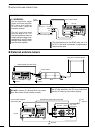
e TUNER CONTROL SOCKET [TUNER] (p. 14)
Accepts the control cable from an optional AH-4
AUTOMATIC ANTENNA TUNER.
r CI-V REMOTE CONTROL JACK [REMOTE] (p. 57)
Designed for use with a personal computer for
remote operation of transceiver functions.
t EXTERNAL SPEAKER JACK [EXT SP] (p. 11)
Connects an 8
Ω external speaker, if desired.
• When an external speaker is connected, the internal
speaker does not function.
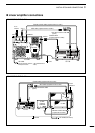
y ACCESSORY SOCKET [ACC] (p. 7)
Enables connection to external equipment such as
an optional AT-180 AUTOMATIC ANTENNA TUNER,
a TNC for data communications or a liner amplifier,
etc.
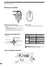
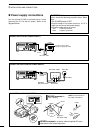
u ELECTRONIC KEYER JACK [KEY]
Accepts a paddle to activate the internal electronic
keyer.
• Selection between the internal electronic keyer and
straight key operation can be made in initial set mode.
i ALC INPUT JACK [ALC]
Connects to the ALC output jack of a non-Icom
linear amplifier.
o SEND CONTROL JACK [SEND] (p. 14)
Goes to ground while transmitting to control
external equipments such as a liner amplifier.
• Max. control level: 16 V DC/2 A
!0 GROUND TERMINAL [GND] (p. 9)
Connects the terminal to ground.
q w e
rtyuio!
0
Rear panel view
When connecting
a straight key
When connecting
a paddle
(dot)
(com)
(dash)
(⊕)