


3
9
INSTALLATION AND CONNECTIONS
n Unpacking
After unpacking, immediately report any damage to the
delivering carrier or dealer. Keep the shipping cartons.
For a description and a diagram of accessory
equipment included with the IC-718, see ‘Supplied
accessories’ on p. 1 of this manual.
n Selecting a location
Select a location for the transceiver that allows
adequate air circulation, free from extreme heat, cold,
or vibrations, and away from TV sets, TV antenna
elements, radios and other electro-magnetic sources.
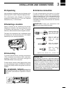
The base of the transceiver has an adjustable stand
for desktop use. Set the stand to one of two angles
depending on your operating conditions.
n Grounding
To prevent electrical shock, television interference
(TVI), broadcast interference (BCI) and other
problems, ground the transceiver through the
GROUND terminal on the rear panel.
For best results, connect a heavy gauge wire or strap
to a long earth-sunk copper rod. Make the distance
between the [GND] terminal and ground as short as
possible.
R WARNING: NEVER connect the
[GND] terminal to a gas or electric pipe, since the
connection could cause an explosion or electric
shock.
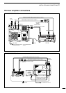
n Antenna connection
For radio communications, the antenna is of critical
importance, along with output power and sensitivity.
Select antenna(s), such as a well-matched 50
Ω
antenna, and feedline. 1.5:1 or better of Voltage
Standing Wave Ratio (VSWR) is recommended for your
desired band. Of course, the transmission line should be
a coaxial cable.
CAUTION: Protect your transceiver from
lightning by using a lightning arrestor.
Antenna SWR
Each antenna is tuned for a specified frequency
range and SWR may be increased out-of-range.
When the SWR is higher than approx. 2.0:1, the
transceiver’s power drops to protect the final
transistor. In this case, an antenna tuner is useful
to match the transceiver and antenna. Low SWR
allows full power for transmitting even when using
the antenna tuner. The IC-718 has an SWR meter to
monitor the antenna SWR continuously
.
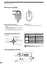
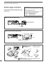
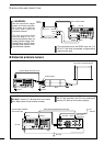
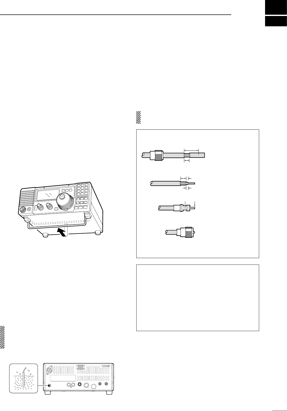
PL-259 CONNECTOR INSTALLATION EXAMPLE
30 mm ≈
9
⁄8 in 10 mm ≈
3
⁄8 in 1–2 mm ≈
1
⁄16 in
30 mm
10 mm (soft solder)
10 mm
1–2 mm
solder solder
Soft
solder
Coupling ring
Slide the coupling ring
down. Strip the cable
jacket and soft solder.
Slide the connector
body on and solder it.
Screw the coupling
ring onto the
connector body.
Strip the cable as
shown at left. Soft
solder the center
conductor.
q
w
e
r