


4
2
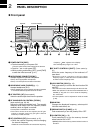
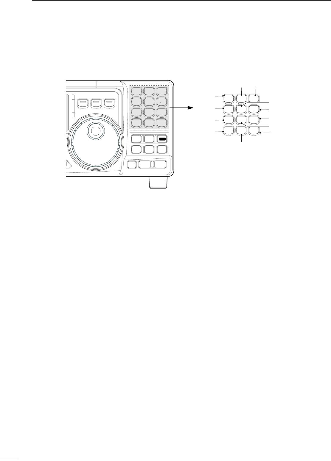
PANEL DESCRIPTION
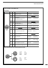
n Front panel (continued)
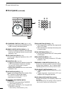
@2 VFO/MEMORY SWITCH/1 [V/M•1] (pgs. 16, 35)
Toggles the operating mode between VFO
mode or memory mode when pushed.
@3 MEMORY WRITE SWITCH/4 [MW•4] (p. 36)
Stores the displayed frequency and operating
mode into the selected memory channel when
pushed for 1 sec.
@4 SPLIT SWITCH/7 [SPL•7] (p. 30)
Turns the split frequency operation ON or OFF
when pushed.
@5 NR SWITCH/. [NR• . ] (p. 23)
Toggles the optional noise reduction function ON
or OFF when pushed. Functions in all modes.
• An optional UT-106 DSP UNIT is required.
• [NR] appears on the display.
Enters noise reduction level set mode when
pushed for 1 sec.
@6 ANF SWITCH/0 [ANF•0] (p. 23)
Toggles the Automatic Notch Filter function ON or
OFF. Functions in SSB and AM modes.
• An optional UT-106 DSP UNIT is required.
• [ANF] appears on the display.
@7 FRQUENCY INPUT/ENTER SWITCH
[F-INP/ENT]
[F-INP/ENT], then keypad then [F-INP/ENT]
— Direct frequency input. (p. 17)
[CH] then [F-INP/ENT], then keypad then
[F-INP/ENT]. Push [CH].
— Direct memory number selection. (p. 35)
@8 SCAN SWITCH/8 [SCAN•8] (p. 39)
Push momentarily to start/stop the programmed
scan in VFO mode.
Push momentarily to start/stop the memory scan
in memory mode.
@9 VOX SWITCH/9 [VOX•9] (p. 27)
Turn the VOX function ON or OFF when pushed
in SSB modes.
#0 M≈V SWITCH/6 [MV•6] (p. 37)
Transfers the memory contents to VFO when
pushed for 1 sec.
#1 MEMORY CLEAR SWITCH/5 [M=CL•5] (p. 38)
Clears the selected readout memory channel
contents when pushed for 1 sec. in memory mode.
• [BLANK] appears above the memory channel number.
#2 VFO SELECT SWITCH/3 [A/B•3] (p. 16)
Toggles between VFO A or VFO B in VFO
mode.
Toggles between transmission VFO and
reception VFO during split operation.
#3 VFO EQUALIZATION SWITCH/2 [A=B•2]
Equalize the frequency and operating mode of the
two VFO’s.
•
The VFO B frequency and operating mode are equalized
with the VFO A frequency and operating mode.
ENT
F-INP
V/M
1
MW
4
A=B
2
M=CL
5
SCN
8
ANF
0
NR
.
A/B
3
VOX
97
SPL
M V
6
#1
#3 #2
#0
@9
@8
@7
@6
@3
@4
@5
@2
MIC
IC-718
PHONES
SQL AF
SHIFT RIT
LOCK
MODE
FILTER
TS
PWR
TUNER
COMP
P.AMP
UP
NB
ATT
SET
CH
DN
ENT
F-INP
V/M
1
MW
4
A=B
2
M=CL
5
SCN
8
ANF
0
NR
.
A/B
3
VOX
97
SPL
M V
6
Z Y