


Document conventions
FortiGate Voice Version 4.0 MR1 Administration Guide
01-410-112851-20100601 11
http://docs.fortinet.com/ • Feedback
Example Network configuration
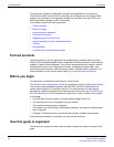
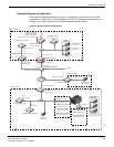
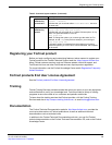
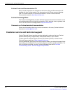
The network configuration shown in Figure 2 or variations on it is used for many of the
examples in this document. In this example, the 172.20.120.0 network is equivalent to the
Internet. The network consists of a head office and two branch offices.
Figure 2: Example network configuration
Port1
Port2 and Port3
Port1: 172.20.120.141
Port2: 10.11.101.100
FortiGate-620B
Cluster
FortiGate-51B
Linksys SRW2008
Windows PC
10.11.101.10
INT: 10.11.101.101
WLAN: 10.12.101.100
SSID: example.com
Password: supermarine
DHCP range: 10.12.101.200-249
FortiWiFi-80CM
FortiGate-82C
Port2: 10.11.101.102
Port1:
172.20.120.130
(sniffer mode)
Port8
(mirror of Port2 and Port3)
Port5
Old Lab
Head office
Linux PC
10.11.101.20
FortiAnalyzer-100B
Port2: 10.11.101.130
Switch: 10.21.101.100
Port4:
10.22.101.100
WAN1: 172.20.120.131
WAN1: 172.20.120.122
Internal: 10.31.101.100
FortiGate-111C
Linux PC
10.21.101.10
FortiGate-3810A
Port1:
10.21.101.101
FortiManager-3000B
Port1:
10.21.101.160
FortiSwitch-5003A
FortiGate-5050SM
Port1: 10.22.101.161
Port1: 10.22.101.104
FortiSwitch-5003A
FortiGate-5050SM
Port1: 10.21.101.161
Port1: 10.21.101.104
FortiGate-5005FA2
Cluster
FortiGate-5005FA2
Port1: 10.21.101.102
Port1: 10.21.101.102
Port1: 10.21.101.103
Branch office
Branch office
Internet
Internal
Network
Windows PC
10.31.101.10
Engineering
Network
10.22.101.0
FortiMail-100C
Port1: 10.11.101.110