


2 Installing the MDW 9040 Pocket Phone System Quick Installation Overview
MDW 9040 Wireless Pocket Phone Installation and Use,
503-801-19012 Issue 2, February 2001
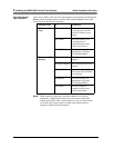
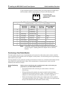
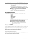
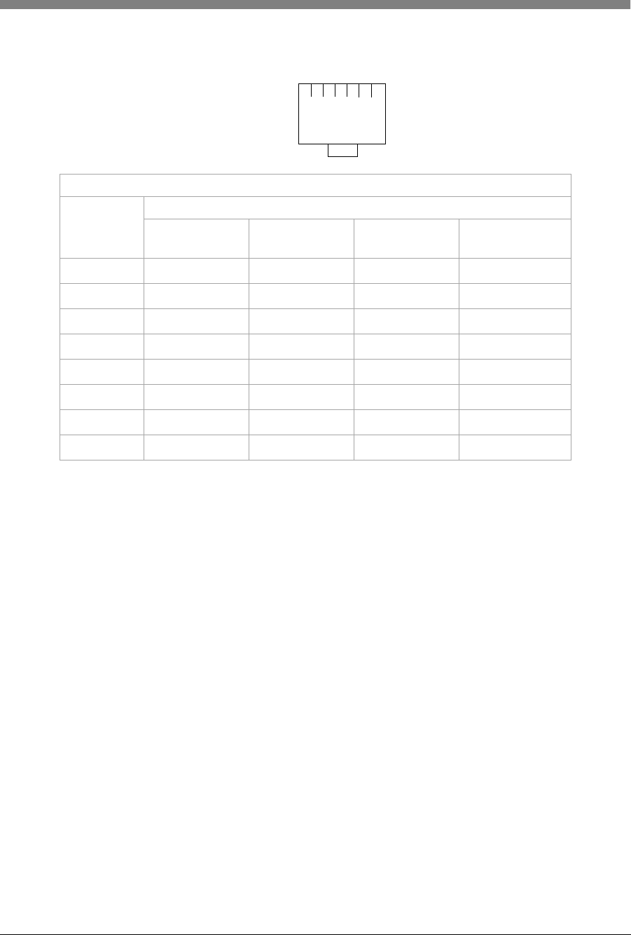
If your installation requires customized wiring, the wiring technician should match
the Pin numbers with the switch interfaces as shown in the following table.
Note: A Dual Radio Module used with an MDW 9040 Wireless Pocket Phone
will NOT support a Tip/Ring [Plain Old Telephone Service (POTS)]
interface.
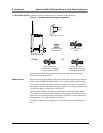
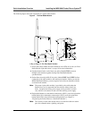
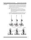
Positioning a Dual Radio Module
The radio modules for each zone of communication can be placed on a flat surface such as a desk or shelf for
ease of installation, OR mounted on the wall (higher is usually better). Use the following rules for positioning a
radio module in your system.
The range depends on your particular operating environment. For indoor use, walls between the handset and the
radio module will reduce the phone’s range. Avoid concentrations of structural metal, such as steel and
aluminum, and reinforced concrete.
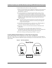
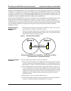
General Positioning
Rules
Failure to observe the following rules regarding location and use will result in poor
performance of your MDW 9040 Pocket Phone.
•
The Synchronization cable connecting two radio modules is 20 inches
(50 cm) long.
• When positioning radio modules, they must be installed with a minimum
separation that is provided by the base “wings” of the radio module (5 1/4”). A
template for wall-mounting the radio modules is provided in Appendix E.
• When wall-mounting the radio module, place it high on the wall for optimum
voice quality and range. Allow 6 to 12 inches (15.2 to 30.5 cm) of space between
the top of the antenna on the radio module and the ceiling.
12
34
5678
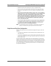
View of Line Jack
(with Dual Radio Module
upside down)
Dual Radio Module LINE 1 and LINE 2 Jack Wiring
Jack Pin # SWITCH TYPE and Radio Module PEC CODE
PARTNER
3204-DRE
MERLIN
3204-DRE
DEFINITY
3204-DRD
MERLIN MAGIX
3204-DRD
1
–Control Tip––
2
– Control Ring – –
3
Control Tip Line Power Pos. – –
4
Voice Ring Voice Ring Ring Ring
5
Voice Tip Voice Tip Tip Tip
6
Control Ring Line Power Neg. – –
7
Aux. Power Neg. Aux. Power Neg. Aux. Power Neg. Aux. Power Neg.
8
Aux. Power Pos. Aux. Power Pos. Aux. Power Pos. Aux. Power Pos.