


2 Installing the MDW 9040 Pocket Phone System Quick Installation Overview
MDW 9040 Wireless Pocket Phone Installation and Use,
503-801-19010 Issue 2, February 2001
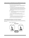
Dual Radio Module
Light Indications
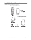
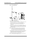
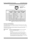
There are two LEDs on the side of the radio module: the System Power LED (labeled
Power) and the Synchronization Controller LED (labeled Control). These LED
indications have the following meanings:
Note: When inserting or replacing a Dual Radio Module in an existing
installation, a different radio module may become the control radio
module (green LED). This is normal. However, only one radio module
can be the control radio module. All other radio modules must be
expansion (amber LED) radio modules.
When this LED is: It indicates:
The Power LED
(Top)
STEADY GREEN The radio module is
receiving power from the
switch or auxiliary power
supply.
NO LIGHT The radio module is not
receiving power, is
connected to the wrong
switch, or has failed.
FLASHING The radio module is in
Registration or Wireless
Test Mode for Line 1.
The Control LED
(Bottom)
STEADY GREEN This is the control radio
module.
STEADY AMBER This is the expansion radio
module.
STEADY RED Either or both handset(s) for
this base are ON and linked
up to the base.
FLASHING The radio module is in
Registration or Wireless
Test Mode for Line 2.
NO LIGHT The radio module is
connected to the wrong
switch or has failed.