


2-5
Linksys SPA9000 Administrator Guide
Document Version 3.01
Chapter 2 Getting Started
Implementing LVS
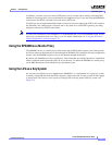
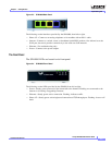
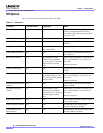
Figure 2-3 SPA9000 Back Panel
The following are the interfaces provided by the SPA9000, from left to right:
• Phone 1/2—Connect to an analog telephone or fax machine with an RJ-11 cable.
• Internet—Connect to a switch, router, or broadband (cable/DSL) modem. Also referred to as the
WAN port, because it provides connectivity to the wide area VoIP network.
• Ethernet—For troubleshooting only.
• Power—Connect to the power adapter.
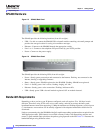
The Front Panel
The SPA9000 LEDs are located on its front panel.
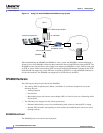
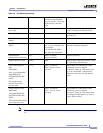
Figure 2-4 SPA9000 Front Panel
The following are the LEDs provided by the SPA900, from left to right:
• Power—Steady green: powered on and connected to the Internet. Flashing: not connected to the
Internet or is booting or upgrading firmware.
• Ethernet—Steady green: active connection. Flashing: indicates traffic.
• Phone 1/2—Steady green: active/registered connection to ITSP through port. Flashing: in use or off
hook.