


2-4
Linksys SPA9000 Administrator Guide
Document Version 3.01
Chapter 2 Getting Started
Implementing LVS
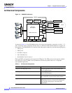
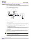
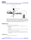
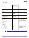
Figure 2-2 Using LVS with SPA9000 and SPA400 as a Key System
When implementing the SPA9000 and SPA400 as a key system, the SPA9000 is connected through a
switch to one or more SPA400s, which are then connected to the existing DID lines from the PSTN. The
SPA9000 has four line interfaces, each of which can support one SPA400 or a single VoIP account with
an ITSP. A single VoIP account with an ITSP can map to multiple DID numbers assigned by the ITSP.
Each SPA400 can support up to four DID lines assigned by the PSTN, so with a SPA400 connected to
all four line interfaces, the SPA9000 can support up to 16 DID lines to the PSTN.
SPA9000 Hardware
The following are the ports provided by the SPA9000:
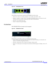
• Two analog (FXS) telephone ports (Phone 1 and Phone 2), which are designed for use by the
following devices:
–
Analog telephone
–
Fax machine
–
Music/audio player with a music source adapter (RJ11-to-Line-In) for use as a Streaming Audio
Server (SAS)
• Two Ethernet ports, designed for the following functions:
–
Ethernet: administrative access for troubleshooting with a directly connected PC or laptop
–
Internet: SIP call traffic and signaling to client stations and administration web server access
(through switch)
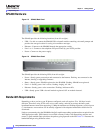
SPA9000 Back Panel
The SPA9000 ports are located on the back panel.
1 to 4 SPA400s
PSTN
Internet
IP Router/
Broadband modem
Hub/switch
Up to 4 DID lines per SPA400
Shared line appearance
SPA9000
Internet (WAN) Interface
ITSP
ISP