


1-12
Linksys SPA9000 Administrator Guide
Document Version 3.01
Chapter 1 Using the Linksys Voice System
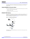
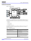
SPA9000 Architecture
Architectural Components
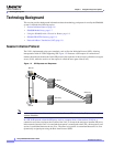
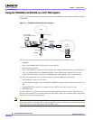
Figure 1-6 SPA9000 Architecture
As shown in Figure 1-6, the SPA 9000 provides four logical line interfaces, referred to as Line 1, 2, 3,
and 4. Each line can be configured with the same or a different ITSP. Each SPA400 also occupies one
line interface. The SPA9000 has five internal clients that register implicitly with the internal SIP proxy:
• FXS1 (fxs1)
• FXS2 (fxs2)
• Call Park (callpark)
• Auto-Attendant (aa)
• Internal Music Server (imusic)
FXS1 and FXS2 correspond to the two physical FXS ports. The FXS ports can only register with the
local SIP proxy. The Call Park is used to maintain calls that are parked, and AA is a scriptable
auto-attendant application.
imusic
Line 1
ITSP SIP Proxy
(408)111-1000 to 7
(949)111-2000 to 7
(888)111-3000 to 7
ITSP SIP Proxy
ITSP SIP Proxy
SPA9000
aa
PSTN
SPA 400
SIP-PSTN
gateway
(408)111-1111
(408)111-1112
(408)111-1113
(408)111-1114
Line 2
Line 3
Line 4
FXS1
Application
server
Switch
FXS2
SIP Proxy
SIP Registrar
Media (RTP) Proxy
Call
park
Administration
web server
Table 1-1 Architectural Components
Architectural Component Function
SIP proxy and Registrar server Accepts registration from client stations and
proxies SIP messages.
Media proxy server Proxies RTP packets between client stations and
proxies SIP messages.
Configuration server Serves configuration files to client stations and
auto configures un-provisioned client stations.
Application server Supports advanced features such as call
park/pickup, directory, directed call pickup and
group paging, hunt groups, and shared line
appearances.