


2-2
Linksys SPA9000 Administrator Guide
Document Version 3.01
Chapter 2 Getting Started
Implementing LVS
Using the SPA9000 and SPA400 as a VoIP PBX System
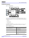
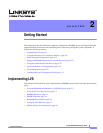
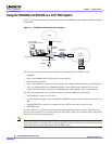
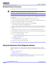
Figure 2-1 illustrates the hardware required to implement a SPA9000 system with the SPA400 connected
to the PSTN.
Figure 2-1 SPA9000 and SPA400 System Hardware
The following are the basic hardware requirements to implement an LVS PBX system:
• SPA9000
• One or more SPA900 series IP Phones (as client stations)
• Ethernet network cables
• One or more Ethernet switches with QoS support and with the required number of available ports
• A PC for configuration of the SPA9000 and other client stations on the network. This can be
connected to the switch or directly to the Ethernet port on the SPA922, 942, or 962 IP phone.
The following components can optionally be added to provide additional functionality:
• FAX machine to send or receive faxes
• A router with QoS support, and a broadband (cable/DSL) modem (gateway) with connectivity to an
ISP
• SPA400 SIP-PSTN gateway for connectivity to the PSTN and local voicemail service
• PSTN DID lines
For best results, use a router and switch that both support Quality of Service (QoS). QoS allows top
priority to be assigned to voice traffic. Otherwise, the quality of the voice connection may suffer when
large files are moved over the network.
Note The SPA9000, the SPA400, and the SPA900 Series IP phones should all be within the same LAN.
Separating the devices through VPN encryption, firewalls, routers, or other devices that affect multicast
traffic may prevent proper functioning of the IP PBX system.
SPA400
(optional)
SPA9000
SPA901, 921, 922, 941, 942, 962
Public
Internet
ITSP
Hub/switch
PC connected
through SPA9x2 IP phone
Up to 4 FXO lines
IP Router/
Broadband
Modem
ISP
Internet (WAN) Interface
PSTN