


Section 7: Infrared Transmission System
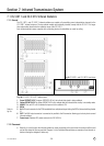
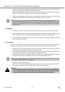
• To cover an entire room, place one infrared radiator in each corner of the conference room, at least 10 feet (3 m)
above the floor, aligning the front panel to face the opposite corner.
Walls and/or ceilings that are painted a dark color, paneled, or acoustically treated will absorb more infrared radi-
ation than white surfaces, so you will need more infrared radiators in darker rooms.
• Sunlight, fluorescent lighting, and photo flashes may weaken infrared radiation. Therefore, try to place the infrared
radiators where they will not be exposed to natural or artificial light or use some extra IRTs.
Note: Working out the exact number of infrared radiators needed for optimum room coverage and placing them cor-
rectly can be a challenge in some rooms. As a rule of thumb, it is better to use many small (CS 5 IRT 1) radia-
tors than only a few large ones (CS 5 IRT 2). If you need assistance, your dealer or nearest AKG Distributor will
be glad to help.
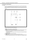
7.1.3 Mounting
• For mobile use, you can fix the support frame of the infrared radiator on a heavy standard loudspeaker stand.
• For permanent installations, you can directly screw the support frame on a wall or ceiling at any desired angle. To
mount a radiator in a corner, you may need additional angle brackets (available from hardware stores).
• To set the tilt angle of the radiator, slacken the set screws on the support frame, rotate the radiator to the desired
angle, and tighten the set screws.
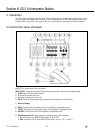
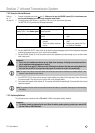
7.1.4 Connections
Important: To avoid damage to any system components, do not lay, connect, or disconnect any cables while power to
the system is on. Always disconnect the entire system from power before making any changes to the wiring.
1. Use RG58 50-ohm coaxial cable and BNC connectors to connect one INFRA OUT jack on the Base Unit rear panel
to the IN BNC jack on the infrared radiator on the left side of the room.
2. Use a cable of the same length (or as nearly as possible) to connect the other INFRA OUT jack on the Base Unit
rear panel to the IN BNC jack on the infrared radiator on the right side of the room.
3. If you need to use more than one radiator on either bus, use RG58 50-ohm coaxial cable and BNC connectors to
connect the OUT jack on the first radiator to the IN jack on the subsequent radiator, and so on.
Note: To ensure consistent performance of the two radiators, keep the difference in length between the two cables
to a practical minimum (less than 164 feet/50 m).
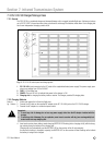
4. Connect each infrared radiator to power.
The CS 5 IRT 1 and CS 5 IRT 2 infrared radiators have no power switches. Therefore, connect the power input on
each radiator to a switched 230 V/50 Hz power outlet protected by an appropriate fuse.
Important:
• If no switched power outlets are available at the site of a permanent installation, ask a qualified elec-
trician to install the required number of outlets in the conference room and a suitable ON/OFF switch
in the control room in accordance with local electrical and occupational safety regulations.
CS 5 User Manual
- 37 -
!