


Section 2: Notes on Wiring and System Examples
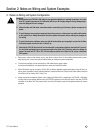
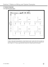
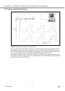
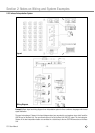
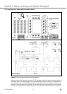
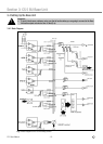
tors. The wiring diagram shows how all microphone stations including the Interpreter Stations are daisy-chained together
in a closed loop.
To ensure stable powering even if one power supply fails, connect one CS 5 PS 12 power supply to the Base Unit, one
CS 5 PS 12 power supply to every sixth microphone station, beginning with the seventh in line counting from the Base
Unit, and connect the last microphone station to the second SYSTEM connector on the Base Unit.
CS 5 User Manual
- 12 -