


Section 3: CS 5 BU Base Unit
3.3 Rear Panel
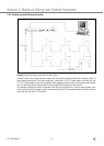
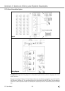
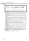
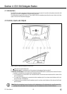
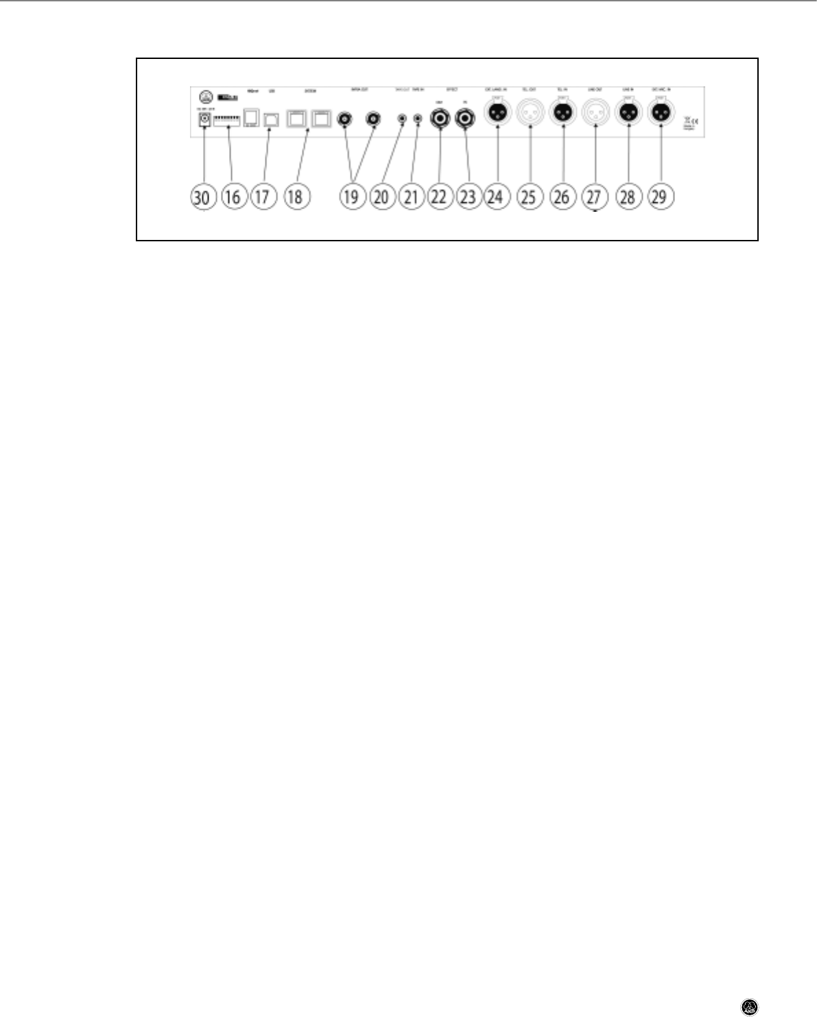
Fig. 2: CS 5 BU rear panel.
16 Dip switches: This set of dip switches allows you to route the various inputs to either the NORMAL bus or the
EFFECTS bus, activate or deactivate NOM limitation on the SYSTEM BUS and LINE OUT outputs, mute the EXT. LANG.
signal. Refer to section 3.4.
17 USB port: Enables the Base Unit to be controlled from a computer. Computer control works best with CS5 VU ad-
vanced delegate stations. The CS5 DU may not provide all the functions that may be required for more complex
systems.
18 SYSTEM: These two RJ 45 connectors provide the inputs, outputs, and power voltage for the microphone stations
connected to the Base Unit. Daisy-chain the microphone stations and connect the last station in the chain to the
second SYSTEM connector on the Base Unit. This makes sure that if one microphone station fails, all other sta-
tions will remain fully functional.
19 INFRA OUT: These two coaxial connectors carry the same signal for the CS5 IRT1 or CS5 IRT2 infrared radiators.
This signal includes the output signals from the interpretation booths (channels 1-6) and the NORMAL bus signal
(channel 0).
20 TAPE OUT: Unbalanced TRS mini jack carrying the NORMAL bus mono signal for recording.
21 TAPE IN: Unbalanced TRS mini jack for connecting the output of an external recording device. The input signal is
fed to the DIRECT/TELEPHONE bus and can be routed to the NORMAL or EFFECTS buses, too.
22 EFFECT OUT: Balanced TRS ¼" jack for sending the EFFECTS bus signal to an external effects device, e.g. a feed-
back eliminator.
23 EFFECT IN: Balanced TRS ¼" jack for receiving the output signal of an external effects device. This signal is fed
to the NORMAL bus.
24 EXT. LANG. IN: Balanced XLR line-level input for an external microphone mixer or AKG wireless microphone re-
ceiver providing an additional interpretation channel. The input signal can be muted or fed to language channel 1
which is part of the infrared signal.
25 TEL. OUT: Balanced XLR connector carrying the output signal of the DIRECT/TELEPHONE bus.
26 TEL. IN: Balanced XLR input for the output signal of a telephone hybrid. The signal is fed to the NORMAL bus.
27 LINE OUT: Balanced XLR connector carrying the NORMAL bus signal for the conference room sound system.
28 LINE IN: Balanced XLR input for a line-level audio source such as a CD player or A/V equipment.
29 EXT. MIC. IN: Balanced XLR microphone-level input with 48-V phantom power for an external hardwire or wire-
less microphone.
30 DC 48V / 3A IN: DC input for connecting the CS5 PS 12 power supply.
CS 5 User Manual
- 14 -