


Section 7: Infrared Transmission System
7.1 CS 5 IRT 1 and CS 5 IRT 2 Infrared Radiators
7.1.1 General
The CS 5 IRT 1 and CS 5 IRT 2 infrared radiators are capable of transmitting seven interpretation channels to the
CS 5 IRR 7 infrared receivers. The two radiator models are technically identical, except that the CS 5 IRT 2 is larger
than and provides about twice the radiation range of the CS 5 IRT 1.
Each infrared radiator comes complete with a mounting bracket for installation on a wall or ceiling.
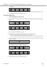
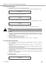
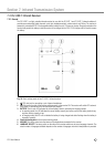
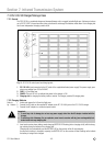
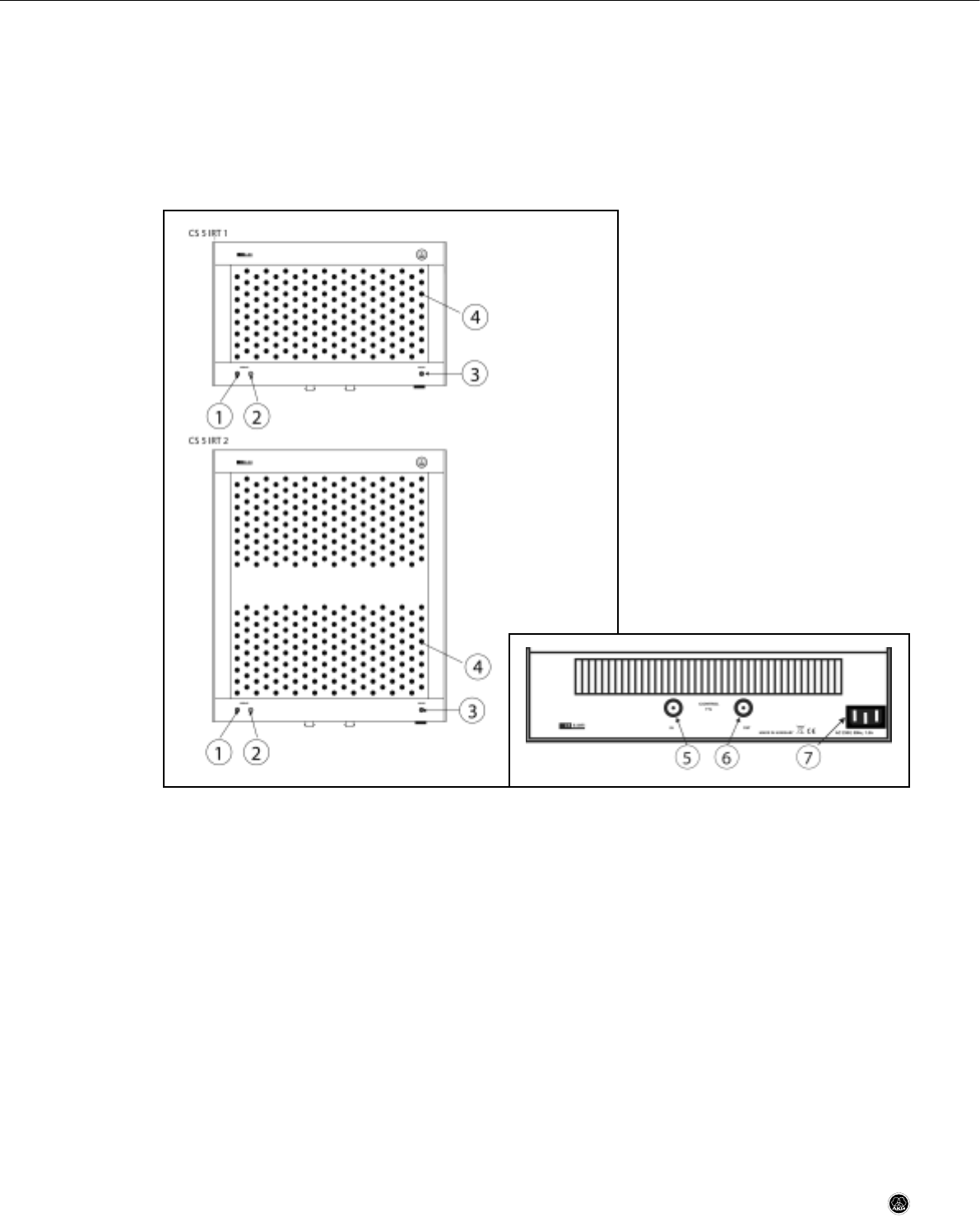
Fig. 9: CS 5 IRT 1 and CS 5 IRT 2 front views.
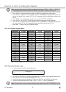
Fig. 9a: CS 5 IRT 1/CS 5 IRT 2 bottom panel.
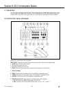
1 Green OPERATE LED: The green OPERATE LED is lit to indicate that signal is being radiated.
2 Yellow OPERATE LED: The yellow OPERATE LED is lit to indicate that the infrared driver circuitry is in standby mode.
3 MAINS: This red LED is lit to indicate that power to the radiator is ON.
4 IREDs
5 IN: BNC input connector for the PPM modulated time-multiplexed signal driving the IREDs (infrared emitting diodes)
(7).
6 OUT: This BNC output connector is connected in parallel to the IN connector allowing you to daisy-chain several
infrared radiators.
7 Power input: Standard IEC power connector for 230 V/50 Hz.
7.1.2 Placement
• Basically, it is best to place the infrared radiators as close as possible to the area where the receivers will be used
and as high above the floor as practical. Diagram 1 in the Quickstart Manual shows an example of two infrared ra-
diators covering the delegates' tables only.
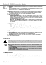
Refer to
fig. 9a.
CS 5 User Manual
- 36 -