


Section 3: CS 5 BU Base Unit
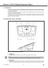
3.4.2 Configuring the Dip Switches
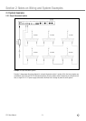
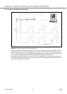
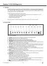
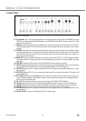
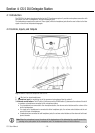
1. Before powering up, set all front panel level controls to minimum (smallest dot) and set the rear panel dip switches
as required. Refer to fig. 3 on page 15 and Table 1 below.
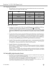
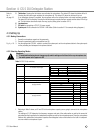
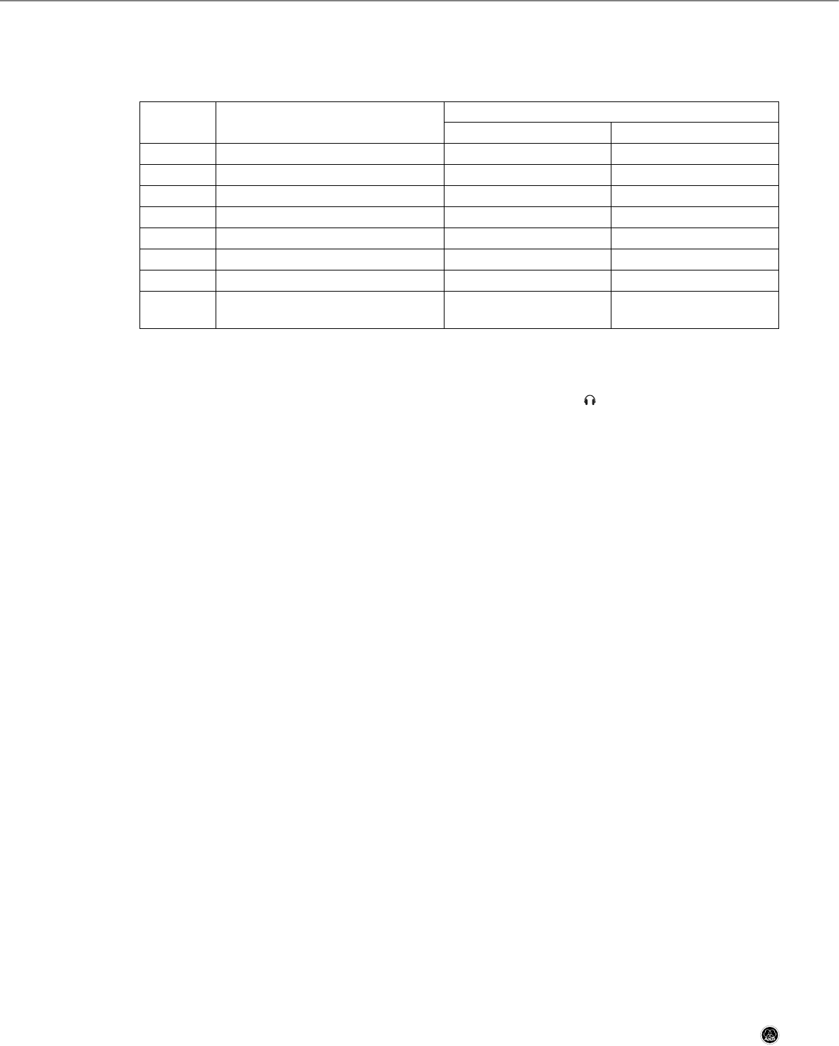
Table 1: Base Unit dip switches.
• Dip switches S1 to S4 route the LINE, EXT. MIC., TAPE, and SYSTEM inputs to either the NORMAL or EFFECTS bus.
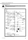
The NORMAL bus feeds the mixed input signals to the TAPE, LINE, SYSTEM, , and INFRA outputs.
The EFFECTS bus signal is available at the EFFECT output where you can connect a feedback eliminator or other
effects device. Connect the output of your effects device to the EFFECT IN jack on the rear panel. The processed
signal is fed to the NORMAL bus. As long as no effects device is connected, the signal is routed to the NORMAL
bus.
• Dip switches S5 and S6 let you activate and deactivate NOM attenuation. NOM (Number of Open Microphones) at-
tenuation reduces the volume of the loudspeakers in a sound system depending on the number of microphones
that are active at any time. The more microphones are open, the more the loudspeaker volume is reduced. S5 al-
lows you to activate NOM attenuation for the loudspeakers on the microphone stations connected to SYSTEM out-
puts. S6 lets you activate NOM attenuation on the LINE OUT signal that feed the room sound system.
• Dip switch S7 allows you to select the input signal for system channel 1. To route the assigned Interpreter Station
output to channel 1, set S7 to "0". To route the EXT. LANG. input to channel 1, set S7 to "1". You can use the lat-
ter configuration for a consecutive interpreter with a hardwire or wireless microphone.
• Dip switch S8 selects one of two microphone activation modes.
- With S8 in position "0", a microphone will be switched on immediately on pressing the talk button ("requesting the
floor") if a microphone channel is available. If no microphone channel is available, the microphone requesting the
floor will be put on the waiting list.
- With S8 in position "1", a microphone will be switched on immediately on pressing the talk button if a microphone
channel is available. If no microphone channel is available, the floor request on top of the waiting list will be deleted
and the last microphone requesting the floor will be added to the waiting list.
3.4.3 Selecting NOM Limitation/Interpretation Channels
• Set NOM LIMIT (7) to the desired ratio between the maximum number of microphones that may be open at any
time and the number of channels available for interpretation.
If no interpretation is needed, you may set NOM LIMIT to "64/0", allowing 64 microphones to be open simultane-
ously. To reduce the number of open microphones, set NOM LIMIT to a lower position.
If interpretation will be provided, set NOM LIMIT for the number of interpretation channels required (e.g., "48/16"
for any number of interpretation channels up to 16 and 48 open microphones).
CS 5 User Manual
- 16 -
Dip switch
Function
Switch position
0 1
S1
routes LINE IN to
NORMAL bus EFFECTS bus
S2
routes EXT. MIC. IN to
NORMAL bus EFFECTS bus
S3
routes TAPE IN to
NORMAL bus EFFECTS bus
S4
routes SYSTEM BUS IN to
NORMAL bus EFFECTS bus
S5
switches NOM attenuation on SYSTEM BUS OUT
OFF ON
S6
switches NOM attenuation on LINE OUT
OFF ON
S7
EXT. LANG. signal
muted routed to Channel 1
S8
Microphone activation mode
Floor request opens available mic channel
or puts microphone on waiting list.
FIFO: Floor request opens available mic
channel or cancels earliest floor request.