


Section 2: Notes on Wiring and System Examples
2.2.3 Infrared Interpretation System
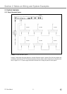
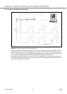
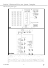
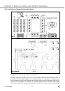
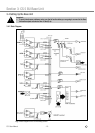
Example 3: Basic layout and wiring diagram for an interpretation system for three conference languages with infrared
signal distribution.
The panel microphones (2 shown in the layout diagram above) are connected to a microphone mixer, which feeds the
LINE IN input on the Base Unit. The room sound system is fed by the Base Unit LINE OUT output. The four Interpreter
Stations in the two interpretation booths are connected in a closed loop to the two SYSTEM connectors on the Base
Unit.
CS 5 User Manual
- 10 -
Layout
Wiring Diagram