


Appendix D. Connector Pinouts
61203153L2-20 Express 3000 User Manual D-3
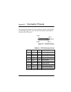
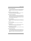
Figure D-3 shows the RJ-11 POTS port interface. For the POTS 1 inter-
face, pin 3 is Ring and pin 4 is Tip. For the POTS 2 interface, pin 3 is
Ring 2 and pin 4 is Tip 2.
Figure D-3. RJ-11 POTS Port Interface
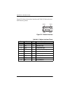
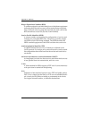
Figure D-4 shows the RJ-45 ISDN line interface. Pin 4 is Ring and pin 5
is Tip.
Figure D-4. RJ-45 ISDN Line Interface
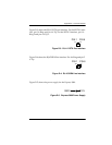
Figure D-5 shows the power supply for the Express 3000.
Figure D-5. Express 3000 Power Supply
PIN 1 PIN 6
ISDN
PIN 1 PIN 8
12V
GND
+
-