


Appendix D. Connector Pinouts
D-2 Express 3000 User Manual 61203153L2-20
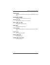
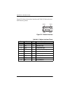
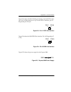
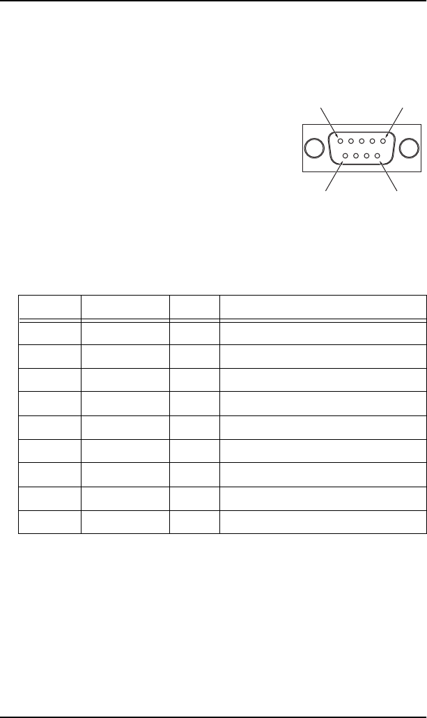
Figure D-2 shows the modem interface and Table D-2 shows the mo-
dem interface pinout.
Figure D-2. Modem Interface
Table D-2.
Modem Interface Pinout
Pin Name I/O Description
1 CD O Carrier Detect
2 RXD O Received Data
3 TXD I Transmitted Data
4 DTR I Data Terminal Ready
5 SG I/O Signal Ground
6 NC - No Connection
7 RTS I Request to Send
8 CTS O Clear to Send
9 NC - No Connection
PIN 5
PIN 9 PIN 6
PIN 1