Appendix A. AT Commands and S-Registers
61203153L2-20 Express 3000 User Manual A-11
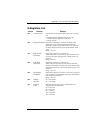
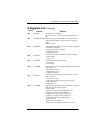
S22 Msg Bits
Miscellaneous message bits.
Bit 4= Bit 5 = Bit 6 = Set: Connects message with baud
rate.
S25 DTR Detect Time
Determines time, in hundredths of a second, that must
elapse before the Express 3000 recognizes a change in
DTR.
Range = 0 to 255
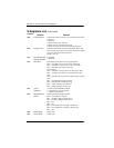
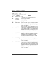
S27 PPP Mode
Value determines whether or not PPP will be a single-link
or multilink connection.
0=Single-link operation (default)
1=Multilink operation
2=Use compression
S30 DTE CTS
Controls the operation of the DTE connector CTS line.
0=Follows RTS
1=Force CTS
S31 DTE RTS
Controls operation of the RTS line.
0=1 ms delay
1=18 ms delay
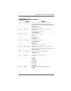
S32 DTE DSR
Controls the operation of the Data Set Ready signal on the
DTE connectors.
0=Force DSR on always
1=DSR off OOS + Test
2=DSR off Link Down
S33 DTE CD
Controls the operation of the Carrier Detect line on the
DTE connectors.
0=Force CD on always
1=CD is active during a call (Normal Operation)
2=Off with LOCD
3=Off link down
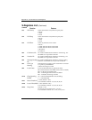
S34 DTE DTR
Determines how the Express 3000 responds to changes in
DTR. This is a bit-mapped register.
0=Ignore DTR
1=Force AT command mode when DTR is off
2=Dump incoming call when DTR is off
4=Hang up incoming call when DTR is off
8=Hang up outgoing call when DTR is off
16=Answer incoming call when DTR is on
28=Idle when off
32=Dial SN0 when DTR is on
64=Dial SN0 when DTR transitions from off to on
S-Registers List
(Continued)
Command
Function Features


