


2-7
Installation
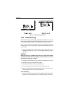
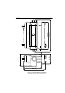
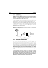
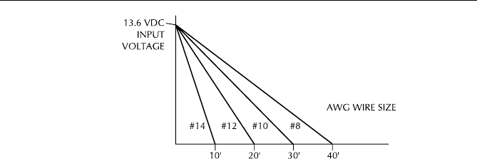
Figure 2-4 Power Cable Length
Your RAY215 should be connected to the nearest primary source of ship's
DC power. A typical source may be a circuit breaker on the power panel
or a fuse block near the unit. When connecting to either of these sources,
the circuit breaker or other in-line fuse should be rated at 10 amps.
It is recommended that lugs be used to connect the power cable to the DC
supply and the lug connections should be both crimped and soldered.
This is very important in order to ensure adequate current draw to the
equipment. Intermittent operation may result if an insufficient connection
is made to the power source. The connection terminal should be clean,
with no sign of corrosion.
The red (+) wire is connected to the positive terminal of the power source.
The black (-) wire is connected to the negative (ground) of the power
source. Should the power connections be inadvertently reversed, the unit
will not power up but no damage will occur. Check the polarity with a
VOM (Voltage/Ohm Meter) and reconnect observing correct polarity. If
the fuse ever needs replacement, be sure to use the same type and rating.
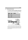
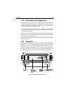
2.4.2 External Speaker Connections
The yellow (+) wire and green (-) wire are used for connecting the RAY215
to an external speaker (see Figure 2-3), such as Raymarine’s 10W External
Speaker (part number E46006).
Four watts of audio output power are provided for an external 4-ohm
speaker. A suitable speaker can be purchased from your local marine dealer.
Connect the yellow (+) wire and green (-) wire to the speaker observing
polarity as it is marked on the speaker. When connected, the external
speaker will function simultaneously with the internal speaker.
CAUTION: DO NOT short the green (-) wire to the yellow (+) wire.
DO NOT short the green (-) wire to the black Power (-) wire.