


2.7 Connection of DECT Portable Stations
96 Installation Manual
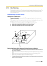
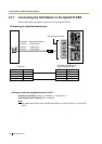
2.7.5 Site Survey Using the KX-TD7590
The PS has a Radio Signal Test mode that monitors the state of the radio link to the CS for site
survey. In the Radio Signal Test mode, the frame loss and signal strength of a synchronous
slot, and the signal strength of the other slots can be measured when the PS is monitoring the
CS. After installing the CSs temporarily as planned during site planning, set the PS to the
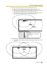
Radio Signal Test mode and locate each CS to measure its coverage area. Then, record the
results on the map of the installation site.
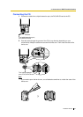
Testing the Radio Signal Strength
After locating the CS(s) temporarily, execute the Radio Signal Test using the PS. The PS scans
whether there is a CS that can link with on channel 0 right after entering the Radio Signal Test
mode. The channel to be scanned can be changed by pressing the appropriate 0 through 9
keys.
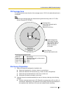
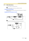
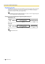
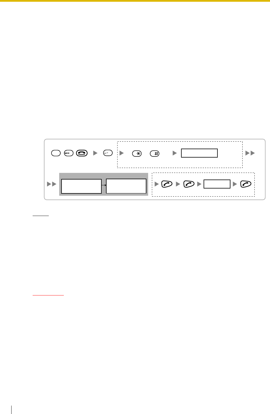
1. Enter the Radio Signal Test mode.
Notes
*1: Channel number
*2: Slot number
*3: When a slot is synchronised, "SYNC" is displayed.
*4: Radio signal strength level
*5: Frame error (0000 to 9999)/Frame counter (0000 to 9999). Frame error indicates the
number of errors out of 10 000 radio signal receptions. Increased number of frame errors
indicates greater radio signal interference and more frequent noise during conversation.
The ideal number of frame error is "0000".
CAUTION
Storing the scan data will clear all directory data.
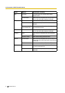
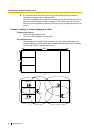
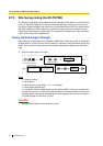
Display example:
RADIO STRENGTH
<<< MEASURING >>>
CH0
*1
SLOT:06
*2
SYNC
*3
L:12
*4
0000/0100
*5
CS-ID:9005301234
0 to 9
Log No.
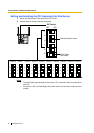
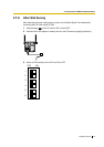
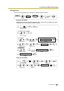
To store the scan data
Press 1, 9, and POWER
for more than 5 seconds.
1
9
9
0
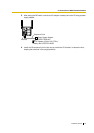
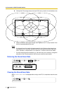
Previous or Next 0 to 9
Channel No.
To survey other slots To survey specific channel
/