


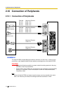
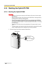
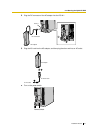
2.10 Connection of Peripherals
136 Installation Manual
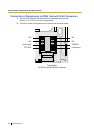
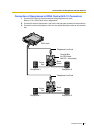
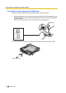
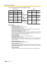
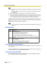
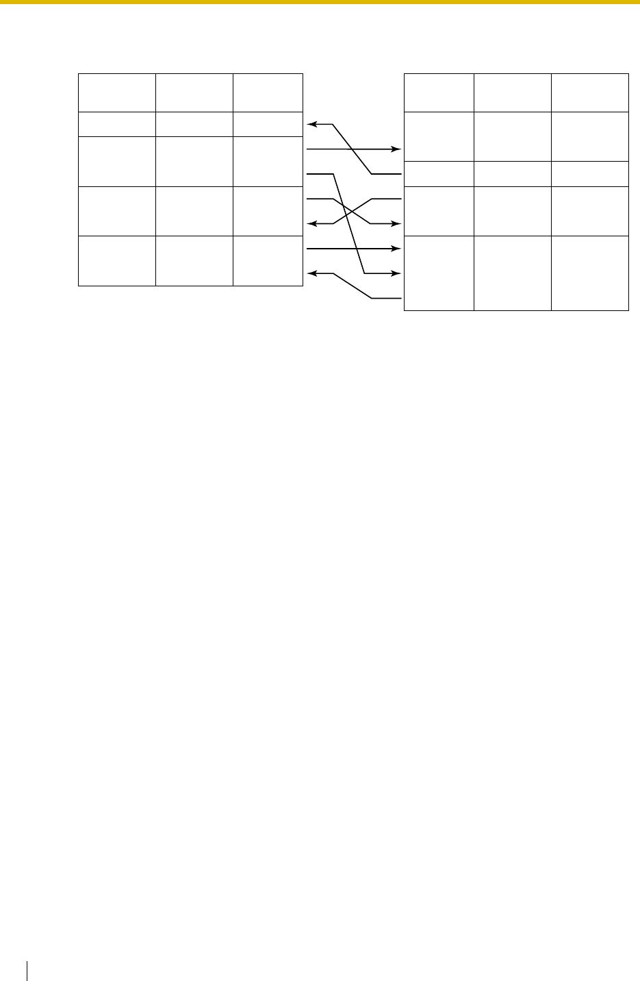
For connecting printer/PC with a 25-pin RS-232C connector
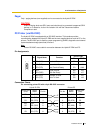
RS-232C Signals
• Received Data (RXD):…(input)
Conveys signals from the printer or the PC.
• Transmitted Data (TXD):…(output)
Conveys signals from the unit to the printer or the PC. A "Mark" condition is held
unless data or BREAK signals are being transmitted.
• Data Terminal Ready (DTR):…(output)
This signal line is turned ON by the unit to indicate that it is ON LINE. Circuit ER (DTR)
ON does not indicate that communication has been established with the printer or the
PC. It is switched OFF when the unit is OFF LINE.
• Signal Ground (SG)
Connects to the DC ground of the unit for all interface signals.
• Data Set Ready (DSR):…(input)
An ON condition of circuit DR (DSR) indicates the printer or the PC is ready. Circuit
DR (DSR) ON does not indicate that communication has been established with the
printer or the PC.
• Request To Send (RTS):…(output)
This lead is held ON whenever DR (DSR) is ON.
• Clear To Send (CTS):…(input)
An ON condition of circuit CS (CTS) indicates that the printer or the PC is ready to
receive data from the unit. The unit does not attempt to transfer data or receive data
when circuit CS (CTS) is OFF.
• Frame Ground (FG)
Connects to the unit frame and the earth ground conductor of the AC power cord.
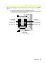
Hybrid IP-PBX Printer/PC
Circuit Type
(EIA)
Signal
Name
Pin No.
Signal
Name
Circuit Type
(EIA)
BB RD (RXD) 2
BA SD (TXD) 3
CD ER (DTR) 4
AB
SG 5
CC
DR (DSR) 6
CA RS (RTS) 7
CB CS (CTS) 8
1FG AA
3 RD (RXD) BB
2 SD (TXD) BA
20
ER (DTR) CD
7
SG AB
5 CS (CTS) CB
6 DR (DSR) CC
CF
4 RS (RTS)
Pin No.