


AD-25182501 CHAPTER 3
Page 43
Revision 1.0.1
NAP- 200-003
Sheet 25/29
Installation of Main Equipment
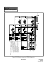
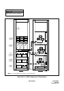
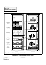
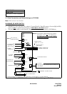
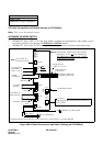
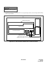
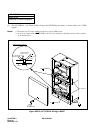
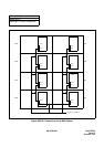
(1) Confirm the connection of the PWR CNT CA-A and power/ringer cables as shown in Figure 003-25 (These
cables are pre-installed).
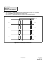
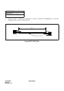
Figure 003-25 Cable Connection between the PZ-PW86 and the BWB
LTC CONNECTOR AREA
PIM
BWB (Back Wiring Board)
PZ-PW86
PWR0B PWR0A
RS
PWR1
PWR CNT CA-A
POWER OUTPUT CABLE (CR,E)
POWER OUTPUT CABLE (+5V, -27V, E)
CARD SLOT AREA