


AD-25182501 CHAPTER 3
Page 19
Revision 1.0.1
NAP- 200-003
Sheet 1/29
Installation of Main Equipment
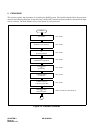
1. Installation of Modules
Install modules according to the installation procedures for Floor Standing, Wall-Mounting or 19-Inch Rack
Mounting installation.
1.1 Installation of the BATTM and MDFM
• Due to weight considerations, it is preferable to Floor-mount the BATTM.
• Always mount the MDF on the wall, at a minimum height of 300mm, in order to comply with AUSTEL
Regulations.
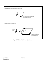
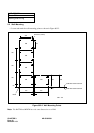
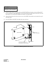
• Refer to Figures 006-1 and 006-2 for cable routing options, and Figures 003-11 to 003-21 for the preferred
modular layouts.
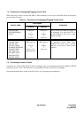
Notes:
1.
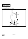
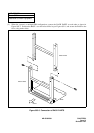
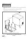
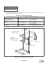
In all cases, the RACK and BASE parts are to be used, as shown in Figures 2-2 to 2-5.
2.
Where the battery and MDF cables pass through a bulkhead, the grommet strip provided must be
added to the aperture, to protect the insulation.
3.
For details of internal cabling for the batteries, see NAP-200-005.
4.
The modular layouts shown are based on the use of ribbon-type LT cables, which terminate on a
connectorised 100-pair Krone block. Standard 10-way disconnect-modules are used for the MDF
jumpers.
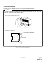
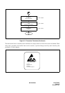
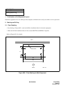
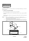
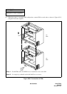
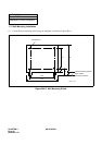
Figure 003-1 Location of the Cable Holes
FRONT
430
RACK PARTS
214
184
30
CABLE HOLE
UNIT: mm