


AD-25182501CHAPTER 1
Page 2
Revision 1.0.1
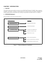
3. HOW TO FOLLOW THE MANUAL
The Installation Procedure is shown by means of flowcharts with a NAP (NEC Action Procedure) Number and the
detail of the work for each step is described in the corresponding NAP.
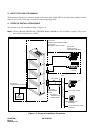
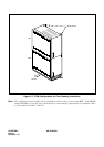
4. SCOPE OF INSTALLATION WORKS
This manual covers the installation shown in Figure 1-2.
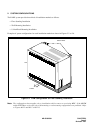
Note:
A Battery Module (BATTM) and a TPF/MDF Module (MDFM) are also available as options. These units
have identical dimensions to a PIM.
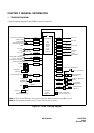
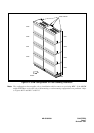
Figure 1-2: Scope of Installation Procedures
NAP- 200-003:
INSTALLATION OF MAIN EQUIPMENT
NAP- 200-008:
MOUNTING OF CIRCUIT CARDS
NAP- 200-004:
INSTALLATION OF
PERIPHERAL EQUIPMENT
SN694
ATTCON
SN611
ATTCON
MDF
MDF CABLES
NAP- 200-006:
CABLE RUNNING
TO MDF
NAP- 200-007:
TERMINATION OF
CABLES ON MDF
D
term
TO C.O. LINE, TIE LINE
ANALOG (SINGLE-LINE)
TELEPHONE
TO TAS INDICATOR, ALARM
INDICATOR
BATTERY
NAP- 200-005:
CONNECTION OF BATTERIES
24 VOLT