


AD-25182501 CHAPTER 3
Page 29
Revision 1.0.1
NAP- 200-003
Sheet 11/29
Installation of Main Equipment
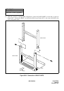
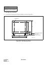
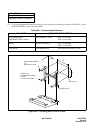
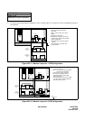
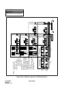
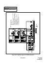
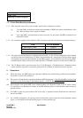
(7) For floor and wall-mounted installations, refer to Figures 003-11 to 003-18 for the recommended layout of
the modules.
Figure 003-11 Modular Layout for 1 PIM Configuration
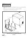
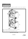
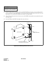
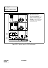
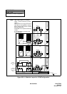
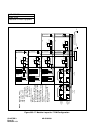
Figure 003-12 Modular Layout for 2 PIM Configuration
10 Pair
10 Pair
10 Pair
10 Pair
10 Pair
MDF0
or
TPF0
PIM0
Notes:- MDF cable lengths are 1.5 metres
- MDF0 must be minimum 300mm
above floor.
- PIM0) - LTC0-2 connect to (L) Krone
(MDF0).
- 240V direct to wall outlet.
- BATTM0 can be supplied for external
battery backup either as MIN. or MED.
backup configuration.
- If BATTM0 is not required use dummy
module.
- If a 78A-H battery is required, add
another BATTM.
LTC0
LTC1
LTC2
PWR SUPPLY
-
+
PS12260
-
+
PS12260
-
+
PS12260
-
+
PS12260
100
Pair
(L)
SHELF 1
MIN. BACKUP,
26 A-H
SHELF 2
MED. BACKUP,
52 A-H
MDF0(L)
MDF0(L)
MDF0(L)
240V AC
+
-
BATTM0
10 Pair
10 Pair
10 Pair
10 Pair
10 Pair
MDF0
or
TPF0
PIM1
Notes: - MDF cable lengths are 1.5 metres
- Can be mounted on floor.
- PIM1 - LTC 1-2 connect to (R) Krone (MDF0)
- LTC0 connect to Krone (MDF0)
- 240V connects to 4 way power board.
- BATTM0 can be supplied for external
battery backup either as MIN. or MED.
backup configuration.
- If BATTM0 is not required use dummy module.
- If a a 78A-H battery is required, add another
BATTM plus dummy module.
LTC0
LTC1
LTC2
PWR SUPPLY
-
+
-
+
-
+
PS12260
-
+
100
Pair
(L)
SHELF 1
MIN. BACKUP,
26 A-H
SHELF 2
MED. BACKUP,
52 A-H
10 Pair
10 Pair
10 Pair
10 Pair
10 Pair
100
Pair
(L)
PWR SUPPLY
MDF0(L)
MDF0(R)
MDF0(R)
LTC0
LTC1
LTC2
MDF0(L)
MDF0(L)
MDFO(L)
Power Board
BATTM0
+
-
240V AC
PIM0