


AD-25182501CHAPTER 3
Page 26
Revision 1.0.1
NAP- 200-003
Sheet 8/29
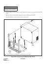
Installation of Main Equipment
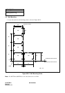
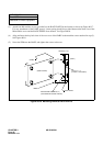
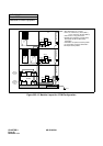
(3) Attach four M4 machine screws (provided) to the RACK PARTS at the location as shown by Figure 003-7.
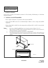
For easy attachment of the PABX, approx. 4 mm spacing should be provided between the inner face of the
M4 machine screw and the RACK PARTS front channel. See Figure 003-8.
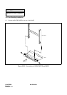
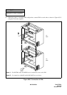
(4) Align and insert the key hole-slots of the rear cover of the PABX to the machine screws attached in step (3).
See Figure 003-8.
(5) Screw the PIM onto the BASE, and tighten the screws at the rear.
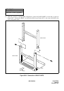
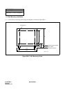
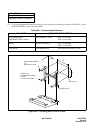
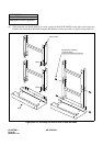
Figure 003-8 Mounting PABX to RACK PARTS
(PABX)
APPROX. 4 mm
(WALL)
SCREW-A (
×
4)
RACK PARTS
M4 MACHINE SCREW-B (x 4)
(REAR COVER)
(LOCALLY PROVIDED)
(PROVIDED WITH RACK PARTS)
BASE