


AD-25182501
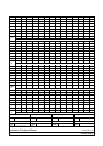
LIST OF ILLUSTRATIONS
Figure Title Page
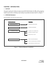
1-1 Reference Manuals for Installation ...................................................................................................... 1
1-2 Scope of Installation Works.................................................................................................................. 2
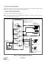
2-1 PABX Trunking Diagram ....................................................................................................................... 3
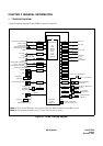
2-2 1-PIM Configuration for Floor Standing Installation........................................................................... 5
2-3 2-PIM Configuration for Floor Standing Installation........................................................................... 6
2-4 8-PIM Configuration for Floor Standing Installation........................................................................... 7
2-5 1-PIM Configuration for Wall-Mounting Installation ...........................................................................8
2-6 4-PIM Configuration for 19-Inch Rack-Mounting Installation ............................................................ 9
3-1 TRC Wiring ............................................................................................................................................ 10
3-2 Static Electricity Guard ......................................................................................................................... 11
3-3 Procedure Flowchart............................................................................................................................. 14
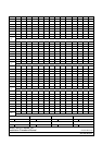
001-1 Unpacking of Main Equipment ......................................................................................................... 16
002-1 Floor Marking for Main Equipment .................................................................................................. 17
002-2 Wall Mounting Points ........................................................................................................................ 18
003-1 Connection of RACK PARTS and BASE..........................................................................................19
003-2 Connection of RACK PARTS............................................................................................................ 20
003-3 Connection of the PIM and the RACK PARTS ................................................................................ 21
003-4 Connection of PIMs ........................................................................................................................... 22
003-5 Wall Mounting Points ........................................................................................................................ 23
003-6 Screwing the RACK PARTS to Wall ................................................................................................. 24
003-7 Mounting the PABX to the RACK PARTS........................................................................................25
003-8 Screwing the RACK PARTS to a Wall .............................................................................................. 26
003-9 Screwing the PACK PARTS and the BASE ..................................................................................... 27
003-10 1 PIM Configuration (19”Rack Mount) .............................................................................................29
003-11 2 PIM Configuration (19”Rack Mount) ............................................................................................. 30
003-12 3 PIM Configuration (19”Rack Mount) ............................................................................................. 31
003-13 4 PIM Configuration (19”Rack Mount) ............................................................................................. 32
003-14 Cable Connections and Switch Settings on PZ-PW86 (Type 1) .................................................... 33
003-15 Cable Connections and Switch Settings on PZ-PW86 (Type 2) .................................................... 34
003-16 Cable Connections and Switch Settings on PZ-PW86 (Type A).................................................... 35
003-17 Cable Connections between the PZ-PW86 and the BWB .............................................................. 36
003-18 PWR CA-A .......................................................................................................................................... 36
003-19 Connection of PWR CA-A ................................................................................................................. 37
003-20 Connection of PWR CA-A ................................................................................................................. 38
003-21 AC Cord-A Wiring to BASE............................................................................................................... 39
003-22 Mounting of the BUS Cards .............................................................................................................. 40
003-23 BUS Cable .......................................................................................................................................... 41
LIST OF ILLUSTRATIONS
Page iii
Revision 1.0.1