


AD-25182501CHAPTER 3
Page 42
Revision 1.0.1
NAP- 200-003
Sheet 24/29
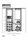
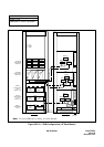
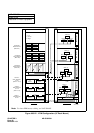
Installation of Main Equipment
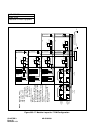
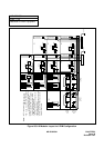
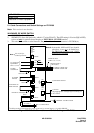
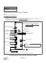
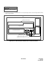
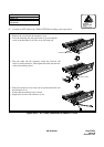
2.2 Cable Connections and Switch Settings on PZ-PW86(A)
Note:
This is now the standard version.
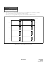
WARNINGS, RE MODE SWITCH
:
1. SEGMENT 1: Set to OFF.
2. SEGMENT 2: Set to “OFF” for 27 volts float, which is optimum for sealed batteries. This setting is also to
be used for periodic boost-charging of EXTERNAL VENTED
batteries.
3. SEGMENT 3: Set to “ON” for 26 volts float, which is the optimum for external vented batteries only.
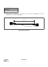
Figure 003-24 Cable Connections and Switch Settings on PZ-PW86(A)
MJ
MN
ON
GND
See
FG
-27V
PWR CNT CA-A
PWR CA-A
BATTERY CABLE/PWR CA-A
TO PWR1
TO OTHER
AC CORD-A
TO AC MAINS INPUT
TO
TO PWR0A CONNECTOR
TO PWR0B CONNECTOR
CONNECTOR
PZ-PW86
TO AUXILIARY
BATT2
BATT1
SW
I
ON
OFF
O
100/
240V
AC INPUT
EQUIPMENT
TO BATTERY OR
OTHER PZ-PW86
GREEN/YELLOW
BLUE
BROWN
TERMINAL ON THE CHASSIS
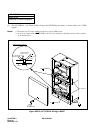
Set the appropriate voltage before turning on
the AC switch.
CAUTION
Note 2:
In Australia, GND and FG are bonded
elsewhere, so are not to be linked here.
The TRC Earth connects to the “GND”
terminal on every PIM.
Note 1:
Set to OFF for
normal operation.
*
*
Cabling method is determined by usage of internal or external battery. See NAP-200-005.
RINGER OUTPUT
CABLE (CR,E)
POWER OUTPUT
CABLE (+5V, -27V, E)
ON
1
2
AC/BATTERY SWITCH
MODE
BATTERY START
120V
AC
MAX: 2.5A DC
Note 2
AC