DEFINITY Communications System
CHAPTER 1: INTRODUCTION
7400B Data Module
User’s Guide
Page 1-3
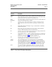
Connector
Description
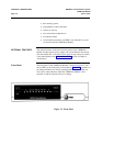
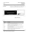
POWER/
TEST
DATA
METERING
AA
CD
RD
SD
TR
OH
CHECK
SPEED
DATA
This red LED lights as long as power is applied to the data module. This LED
flashes during any test mode, except the start-up self-test. It also flashes along
with the DATA LED if the connection with the PBX is lost.
This red LED lights to indicate the state of the CTS (Clear To Send) output lead
when the Data Metering option is enabled.
Automatic Answer. This red LED flashes to indicate an incoming call and
lights continuously when the data module is operating in Automatic Answer
mode.
Carrier Detect. This red LED lights as long as communication is established
with the far end device.
Receive Data. This red LED lights when received data is being transferred
from the 7400B Data Module to the local terminal device.
Send Data. This red LED lights when transmitted data is being transferred from
the local terminal device to the 7400B Data Module.
Terminal Ready. If the &d0 option is enabled, the red LED is on continuously;
if either the &d1 or &d2 option is enabled, this LED indicates the state of the
DTR lead (see description of &d command in Appendix A).
Off Hook. This red LED lights continuously from the time a data
communications call is initiated until the call is terminated.
This red LED lights when a call set up fails because of an incompatibility
between the configuration of the local terminal device and the far end device.
The incompatibility will usually occur if a common operating speed cannot be
achieved between the two endpoints. Chapter 5, “Troubleshooting,” provides
information about this and other conditions that may cause this LED to light.
This green LED lights to indicate that a data call is in progress. This LED
flashes along with the POWER/TEST LED if the connection with the PBX is
lost.
TABLE 1-1 Front Panel LED Indicator Descriptions


