


Installation
3-6
Copyright © 2005-2006 Eaton Corporation. All Rights Reserved.
IPN 997-00012-41D December 2006
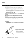
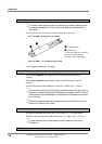
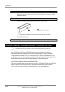
Step 3 – Fit cables and sleeves
To maintain safety approvals insert only the following numbers of cables per clamp,
with sleeves where applicable. This will ensure that cables are retained correctly in
their clamps.
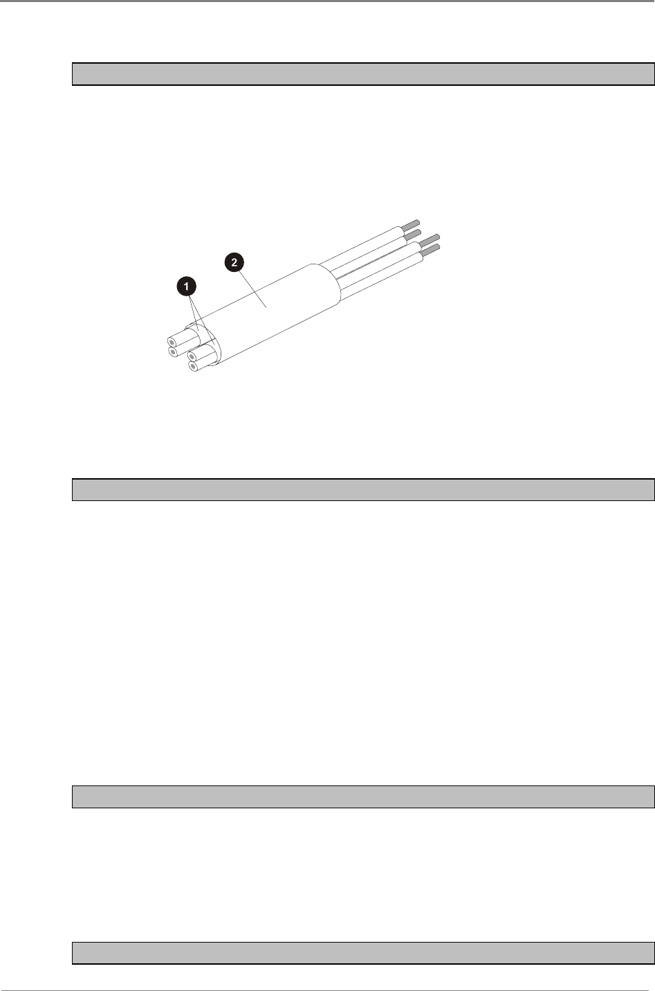
Feed the cables through the clamps as follows, depending on cable size:
1mm
2
(18 AWG) – 2 cable pairs* per clamp:
" 2 x 5mm sleeves
# 10mm sleeve
* If only one cable pair is required
then use a dummy pair with
sleeves to make up the space.
4mm
2
(12 AWG) – 1 or 2 cable pairs per clamp
Do not tighten the clamps at this stage.
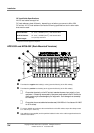
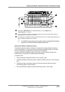
Step 4 – Terminate cables
Terminate the negative load cable(s) at the (-) terminal block(s) of the DC
outlet(s).
Terminate the positive load cable(s) at the (+) terminal block(s) of the DC
outlet(s).
Tighten the terminal screws. Required torque: 0.4 – 0.6 Nm (3.5 – 5.3 lb-in).
Ensure that the polarity at the DC outlet(s) matches the power input polarity of your
equipment. Connecting reverse polarity equipment power cables to the DC outlets of
a power system might cause damage to your equipment. Such damage is not covered
by our warranty.
Ensure that the correct cable sizes have been used (1mm
2
/18 AWG for 6 A outlets
and 4mm
2
/12 AWG for 25 A outlets).
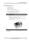
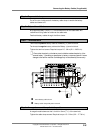
Step 5 – Arrange sleeves and tighten clamp screws
Arrange the sleeves so that they are all within 10mm (
3
/
8
”) of the terminals.
Tighten all cable clamp screws. Required torque: 1.5 – 2 Nm (13.2 – 17.7 lb-in).
Tighten the screws of any unused clamps to prevent access to the DC output
terminations.
Procedure complete