


DC Installation Practices
Copyright © 2005-2006 Eaton Corporation. All Rights Reserved.
IPN 997-00012-41D December 2006
3-3
Important Notes for Rack Mounted Systems:
• If this DC power system is installed in a closed or multi-unit rack assembly ensure that
the ambient temperature is less than 40°C.
• Ensure that the air flow is not restricted.
• Ensure that the system’s weight is adequately and evenly supported.
• Take note of the maximum AC current stated on the nameplate. Ensure that the AC
supply is correctly rated.
• Ensure that reliable earthing is maintained. Carefully check earth continuity from the
branch circuit to the DC power system.
DC Installation Practices
Before you start connecting the DC load and battery cables (if applicable) to a power system,
please read the following DC Installation Practices:
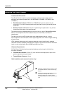
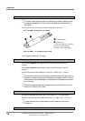
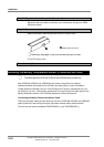
• On APS3-06X (desktop versions), run the DC load cables through the supplied nylon
strain relief clamps at the rear. (See page 3-
5 for details.) Failure to fit the strain relief
clamps and using the incorrect torque setting for tightening their captive screws voids all
safety approvals.
• To easily distinguish between positive and negative load cables, we recommend using
cables with different colors (as specified by local wiring regulations). The same applies
to battery cables (if applicable).
• To reduce inductive coupling, separate DC load, battery and communications cabling
from AC supply cables. If the cables have to cross, run them at right angles to the AC
supply cables.
• In order to minimize parasitic cable inductance and reduce electromagnetic interference
(EMI), all DC load cables should be routed in close proximity to one another, and large
current loops should be avoided. The same applies to battery cables (if applicable).
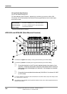
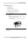
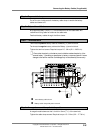
Connecting the DC Load Cables
Eight DC outlets (labeled 1 to 8) are available for connecting your equipment power cables.
Each DC outlet is protected by a corresponding 6 A or 25 A circuit breaker (accessible from
the DC distribution at the front). The current rating of the corresponding circuit breaker
determines the current rating of a DC outlet.
The DC outlets are floating to meet the isolation requirements for powering
Power over Ethernet IEEE802.3af compatible devices. In non-Power over Ethernet applications
the positive or negative output of the DC outlets can be referenced to earth, if required.