


1.3. INSTALLATION
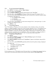
1.3.1. Identify Your Existing Wiring System
For you to properly connect your 2750 4-Line Telephone to an existing wiring system, it is important
that you understand its configuration. The following are the most common multiple line situations.
They consist of either one or both types of standard telephone jacks: The RJ11 Single Line Jack and the
RJ14 Double Line Jack. Your system should match one of them.
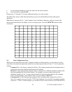
1.3.2. Plan Your Installation
Up to 16 Cortelco 4 Line Telephones may be connected together. You may connect 2750, 2740 or 2742
4-Line Telephones to form your office/home configuration. Each device must be assigned a different
station number, from 01 to 16. Until a telephone is assigned a station number, the telephone will not
function correctly. Station 01 will be the first station to be assigned. See Section 2.1 Station Number
Assignment.
NOTE: Each 4-line telephone must be connected to the same Line 1 telephone number for proper
operation. The remaining lines may or not be connected to each station.
1.3.3. Standard Installation:
Your 2750 telephones come factory-set for a standard installation, which is also called “square” in
telephone terminology. This means that Line 1 is to be connected to the same Line 1 telephone number
at all the stations, Line 2 is to be connected to the same Line 2 telephone number at all the stations, and
so on for Lines 3 and 4. This is the desired setup for most installations, and if this is how you will be
connecting your 2750, you do not need to change any of the line connection settings in the telephones.
You need only connect the phones to the telephone lines.
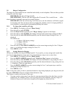
1.3.4. Installations with Private Lines and Unconnected Lines:
You may connect private lines to Lines 2, 3 or 4 at some or all of your telephones. A private line is a
telephone number that is connected to only one station. It is not shared with any other 4 line station.
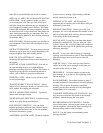
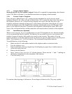
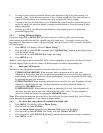
1.3.5. Desk Mount
a. Connect the power adapter to the jack on the bottom of the phone. Plug the adapter into a wall
outlet which is not controlled by a wall switch. Use only a 9V DC 500mA, Class 2 adapter.
b. Connect the line cords. See Section 1.3.8.
c. Select the desired viewing angle and install the desk stand. The desk stand can be installed in
two positions to give a choice of viewing angle.
d. Plug the coiled cord into the handset jack, and plug the other end of the cord into the base.
e. Place the handset on the base.
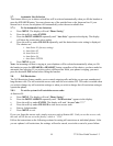
1.3.6. Wall Mount
a. Remove the desk stand. The unit will then mount directly on a standard wall telephone jack.
b. Connect the power adapter and the line cords. See Steps 2 and 3 above.
c. Mount telephone to wall jack (RJ-11W).
d. Plug the coiled cord into the handset, and then plug the other end of the cord into the base.
e. Rotate the handset hook into the wall mount position and place the handset on the base.
7 2750 User Guide Version 1.3