


B-61
Cisco SIP IP Phone 7960 Administrator Guide
78-10497-02
Appendix B SIP Call Flows
Call Flow Scenarios for Failed Calls
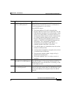
Step Action Description
1
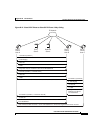
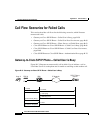
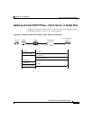
Setup—PBX A to Gateway 1 Call Setup is initiated between PBX A and Gateway 1. The
Call Setup includes the standard transactions that take
place as User A attempts to call User B.
2
INVITE—Gateway 1 to Cisco
SIP IP phone
Gateway 1 maps the SIP URL phone number to a dial-peer.
The dial-peer includes the IP address and the port number
of the SIP enabled entity to contact. Gateway 1 sends a SIP
INVITE request to the address it receives as the dial peer
which, in this scenario, is the Cisco SIP IP phone.
In the INVITE request:
•
The IP address of the Cisco SIP IP phone is inserted in
the Request-URI field.
•
PBX A is identified as the call session initiator in the
From field.
•
A unique numeric identifier is assigned to the call and
is inserted in the Call-ID field.
•
The transaction number within a single call leg is
identified in the CSeq field.
•
The media capability User A is ready to receive is
specified.
•
The port on which the Gateway is prepared to receive
the RTP data is specified.
3
Call Proceeding—Gateway 1 to
PBX A
Gateway 1 sends a Call Proceeding message to PBX A to
acknowledge the Call Setup request.
4
100 Trying—Cisco SIP IP phone
to Gateway 1
The Cisco SIP IP phone sends a SIP 100 Trying response
to Gateway 1. The 100 Trying response indicates that the
INVITE request has been received by the Cisco SIP IP
phone.
5
180 Ringing—Cisco SIP IP
phone to Gateway 1
The Cisco SIP IP phone sends a SIP 180 Ringing response
to Gateway 1. The 180 Ringing response indicates that the
user is being alerted.
6
Alerting—Gateway 1 to PBX A Gateway 1 sends an Alert message to PBX A.