


B-11
Cisco SIP IP Phone 7960 Administrator Guide
78-10497-02
Appendix B SIP Call Flows
Call Flow Scenarios for Successful Calls
Gateway to-Cisco SIP IP Phone—Successful Call Setup and Call
Transfer
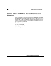
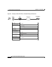
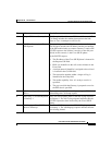
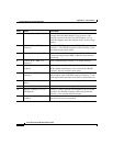
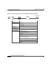
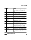
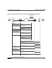
Figure B-3 illustrates a successful gateway-to-Cisco SIP IP phone PC call setup
and call transfer without consultation. In this scenario, there are three end users:
User A, User B, and User C. User A is located at PBX A. PBX A is connected to
Gateway 1 (SIP Gateway) via a T1/E1. User B is located at a Cisco SIP IP phone
and is directly connected to the IP network. User C is located at PBX B. PBX B
is connected to Gateway 2 (SIP Gateway) via a T1/E1. Gateway 1, Gateway 2, and
the Cisco SIP IP phone are connected to one another over an IP network.
The call flow is as follows:
1.
User A calls User B.
2.
User B answers the call.
3.
User B transfers User A’s call to User C and then hangs up.
4.
User C answers the call.