


10 DSR1021/1022 Switch Installer/User Guide
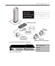
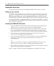
2. Attach one end of the CAT 5 patch cable to the RJ-45 connector on the DSRIQ module.
Connect the other end of the CAT 5 patch cable to the desired port on the back panel of the
DSR1021/1022 switch.
3. Repeat this procedure for all servers you wish to attach.
NOTE: When connecting a Sun DSRIQ module, you must use a multi-sync monitor in the local port to
accommodate Sun computers that support both VGA and sync-on-green or composite sync.
To connect a DSRIQ module to a serial device:
1. Attach the DSRIQ-SRL module 9-pin serial connector to the serial port of the device you will
be connecting to the DSR1021/1022 switch.
2. Attach one end of the CAT 5 patch cable to the RJ-45 connector on the DSRIQ-SRL module.
Connect the other end of the CAT 5 patch cable to the desired port on the back panel of the
DSR1021/1022 switch.
NOTE: The DSRIQ-SRL module is a DCE device and supports only VT100 terminal emulation.
3. Connect the power supply to the power connector on your DSRIQ-SRL module. The cable
expander can be used to power up to four DSRIQ-SRL modules from a single power supply.
4. Connect the DSRIQ-SRL module power supply to an appropriate AC wall outlet. Power up
your serial device. See
Appendix C on page 80 for more information on DSRIQ-SRL modules.
Verifying the Connections
Verify the connections between the DSR1021/1022 switch, DSRIQ modules and serial devices by
reading the status of the LEDs on the DSR1021/1022 switch and the DSRIQ module.
DSR1021/1022 switch
The front panel of the DSR1021/1022 switch features two LEDs indicating the
Ethernet
connection.
• The top green LED, labeled Link, illuminates when a valid connection to the network is
established and blinks when there is activity on the port.
• The lower amber LED, labeled 100M, indicates that you are communicating at the 100 Mbps
rate when using an Ethernet connection.
Additionally, the two LEDs above each port number on the front panel of the DSR1021/1022
switch indicate the target device status.
• The green LED illuminates when the attached target device is powered on.
• The amber LED illuminates when that port is selected.