Chapter 2: Installation 9
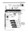
2. Plug the VGA monitor and PS/2 keyboard and mouse cables into the corresponding
DSR1021/1022 switch ports. You must install both a keyboard and mouse on the local port, or
the keyboard will not initialize properly.
3. Choose an available numbered port on the back panel of the DSR1021/1022 switch. Plug one
end of a CAT 5 patch cable (4-pair, up to 10 meters) into the selected port and plug the other
end into the RJ-45 connector of a DSRIQ module.
4. Plug the DSRIQ module into the corresponding ports on the back panel of the target server.
Repeat this procedure for all servers that are to be connected to the DSR1021/1022 switch. See
the
To connect a DSRIQ module to a server procedure on page 9 and the To connect a DSRIQ
module to a serial device procedure on page 10 for more information.
5. Plug a CAT 5 patch cable from your Ethernet network into the LAN port on the back of the
DSR1021/1022 switch. Network users will access the DSR1021/1022 switch through this port.
6. (Optional) The DSR1021/1022 switch can also be accessed using a ITU V.92, V.90 or V.34-
compatible modem. Plug the 9-pin serial cable into the MODEM port on the back of the
DSR1021/1022 switch. Plug the other end into the connector on the modem.
NOTE: Using a modem connection instead of a LAN connection will limit the performance capability of your
DSR1021/1022 switch.
7. (Optional) Plug one end of the cable supplied with the SPC power control device into the SPC
port on the DSR1021/1022 switch and plug the other end into an SPC device. Plug the power
cords from the target servers into the SPC device power outlets. Plug the SPC device into an
appropriate AC wall outlet.
8. If you are configuring the DSR1021/1022 switch using the console menu interface, use the
supplied null modem cable to connect a terminal or PC running terminal emulation software
(such as HyperTerminal
®
) to the SETUP port on the back panel of the DSR1021/1022 switch.
Set the terminal to 9600 bits per second (bps), 8 bits, 1 stop bit, no parity and no flow control.
9. Power up each target device and then power up the DSR1021/1022 switch. After
approximately one minute, the switch completes initialization and displays the OSCAR
®
graphical user interface Free tag on the local port monitor.
10. If you did not use the console menu interface to configure the DSR1021/1022 switch, use the
DSView 3 software to configure the switch. See the DSView Installer/User Guide or the
DSView 3 Online Help for detailed instructions.
To connect a DSRIQ module to a server:
1. Attach the color-coded connectors of a DSRIQ module to the corresponding keyboard,
monitor and mouse ports on the server you will be connecting to the DSR1021/1022 switch.


