


33
ZB2430 User’s Manual - v1.6
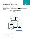
CONFIGURING THE ZB2430
www.aerocomm.com
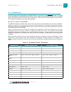
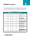
Read Digital Input
The OEM Host issues this command to read the state of GI0 input
pins. Pins configured as outputs will report their current state.
Command: <0xCC> <0x20>
Number of Bytes Returned: 2
Response: <0xCC> <Digital In>
Parameter Range:
<Digital In> = bit-0: GI0
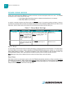
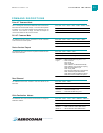
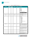
Read ADC
The OEM Host issues this command to read the onboard 12-bit A/D
converters.
This command allows a very detailed amount of customization. The
OEM Host can select which pin or sensor to monitor, the resolution
of the measurement and the reference voltage to measure the input
ADC against.
Greater Resolution will provide a more detailed response, but will
introduce additional latency.
The following equations can be used to determine the voltages
associated with the ADC value returned:
Command:<0xCC> <0x21> <Channel> <Resolution> <Ref>
Number of bytes Returned: 3
Response: <0xCC> <Hi ADC> <Lo ADC>
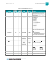
Parameter Range:
<Channel> = 0x00: Cmd/Data
0x01: InRange
0x02: GI03
0x03: GI04
0x04: GI05
0x05: GI06
0x06: GI07
0x07: GI08
0x0D: Positive Voltage Reference = 1.25V
0x0E: Temperature Sensor
0x0F: Vdd
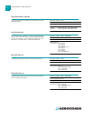
<Resolution>= 0x00: 8 bit resolution [RES=0x00FF]
0x01: 10 bit resoltution[RES=0x03FF]
0x02: 12 bit resolution [RES=0x0FFF]
0x03: 14 bit resolution [RES=0x3FFF]
<Reference>= 0x00: Internal 1.25V [REFvoltage= 1.25V]
0x01: External Reference on GI08
0x02: Vdd
0x03: Differential between pins GI07 and Gi08
<Hi ADC> = MSB of requested 12-bit ADC value
<Lo ADC> = LSB of requested 12-bit ADC value
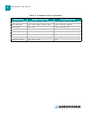
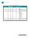
Write Digital Outputs
The OEM Host issues this command to write both digital output lines
to particular states.
The OEM Host must write the value of all digital outputs at once.
Each bit represents a GIO. The first 8 bits are resserved and not in
use.
Command: <0xCC> <0x23> <Digital Out[1-0]>
Number of Bytes Returned: 2
Response: 0xCC <Digital Out [1-0]>
Parameter Range:
<Digital Out>= bit-0: GO0
bit-1: GO1
bit-2: GO2
bit-3: GO3
bit-4: GO4
bit-5: GO5
bit-6: GO6
bit-7: GO7
bit-8-15 : Reserved
Set Max Power
ADIn
ADC value
RES[]
---------------------------
⎝⎠
⎛⎞
= REFvoltage[]×