


5
ZB2430 User’s Manual - v1.6
SPECIFICATIONS
www.aerocomm.com
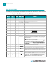
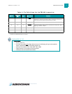
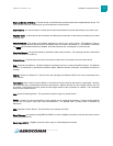
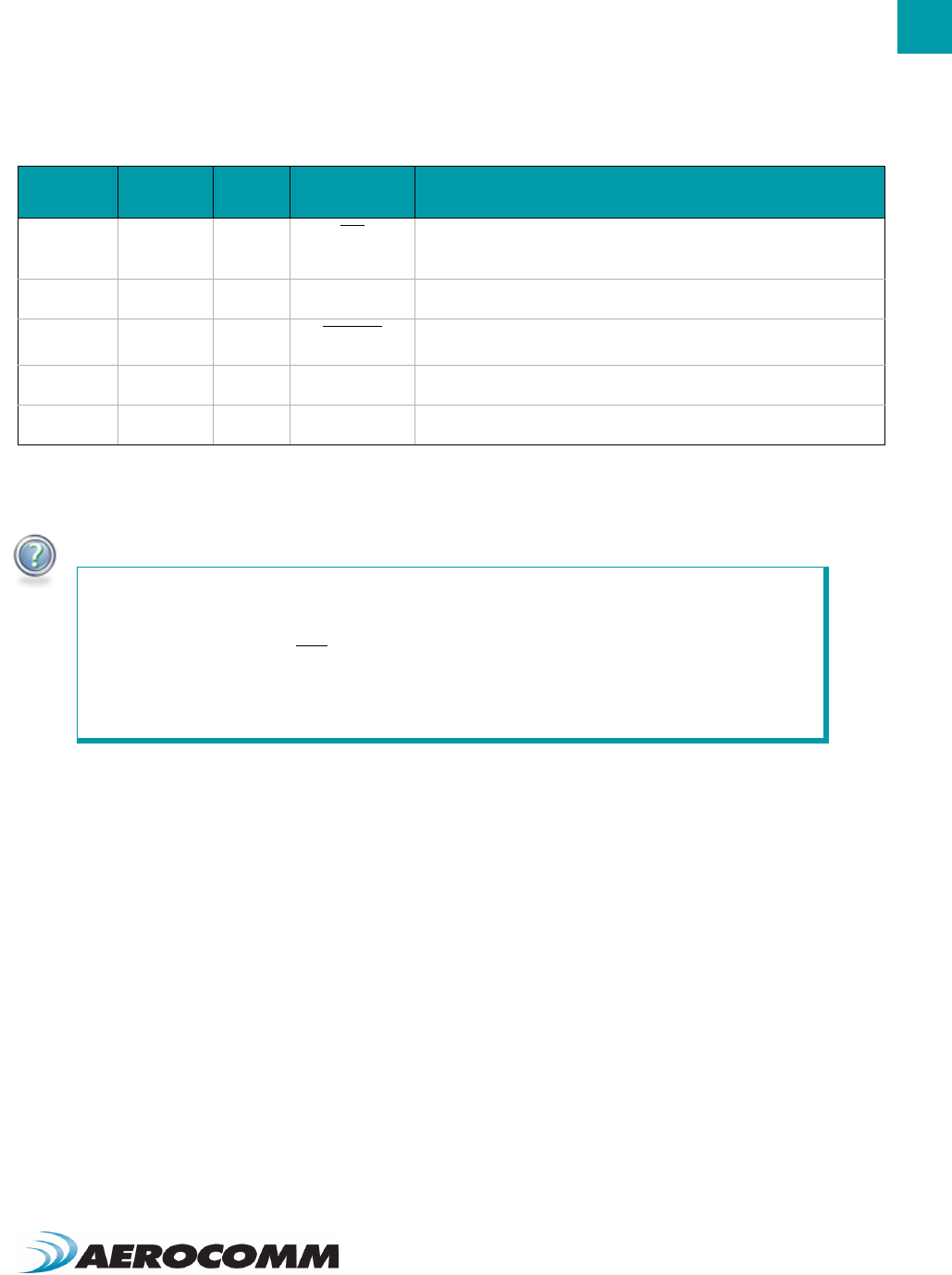
18 12 O CTS Clear to Send - Active Low when the transceiver is ready to accept data for
transmission. High when input buffer is filling. Contining to send data when
CTS is high can cause buffer overflow and the loss of data.
19 14 I/O GIO_8 / AD_5 Has Internal connection. Reserved for future GPIO.
20 13 O Sleep Ind. Sleep mode indicator. When logic Low, transceiver is in sleep mode. When
logic High, transceiver is awake.
21 17 I/O GIO_6 / AD_3 Has Internal connection. Reserved for future GPIO.
22 15 I GIO_7 / AD_4 Has Internal connection. Reserved for future GPIO.
1. May be left disconnected on ZB2430-D devices.
2. Feature not implemented at time of release.
ENGINEER’S TIP
Design Notes:
• All I/O is 3.3V TTL.
• All inputs are weakly pulled High (20k) and may be left floating during normal operation.
When implemented, RTS
will be weakly pulled Low.
• Minimum Connections: VCC, VPA, GND, TXD, & RXD.
• Signal direction is with respect to the transceiver.
• Unused pins should be left disconnected.
Table 2: Pin Definitions for the ZB2430 transceiver
SMT Pin
Pluggable
Pin
Type Signal Name Function