


Mechanical Installation & Cabling MultiVOIP User Guide
98
Connect the other end to the trunk line.
Verify that the E&M Type in the E&M Options group of the Interface
dialog box is the same as the E&M trunk type supported by the
telephone switch. See Appendix B for an E&M cabling pinout.
For a DID connection.
(DID Example: DID fax system or DID voice phone lines.)
Connect one end of an RJ-11 phone cord to the Channel 1 FXS/FXO
connector on the back of the MultiVOIP.
Connect the other end to the DID jack.
NOTE
: DID lines are polarity sensitive. If, during testing, the DID line
rings busy consistently, you will need to reverse the polarity of
one end of the connector (swap the connections of the wires to
the two middle pins of one RJ-11 connector).
6. Repeat step 5 to connect the remaining telephone equipment to each
channel on your MultiVOIP. Although a MultiVOIP’s channels are
often all configured identically, each channel is individually
configurable. So, for example, some channels of a MultiVOIP might
use the FXO interface and others the FXS; some might use the DID
interface and others E&M, etc.
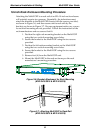
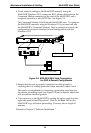
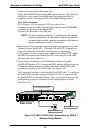
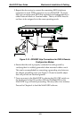
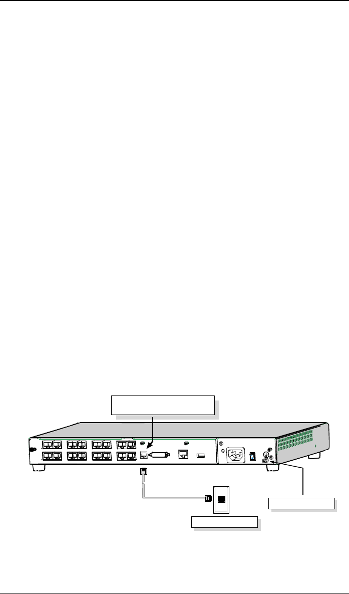
7. If you intend to configure the MultiVOIP remotely using the
MultiVOIP Windows GUI, connect an RJ-11 phone cable between the
Command Modem connector (at the rear of the MultiVOIP) and a
receptacle served by a telco POTS line. See Figure 3-13.
The Command Modem is built into the MultiVOIP unit. To configure
the MultiVOIP remotely using its Windows GUI, you must call into
the MultiVOIP’s Command Modem. Once a connection is made, the
configuration process is identical to local configuration with the
Windows GUI.
COMMAND
10 BASET
E&M FXS/FXO
E&M FXS/FXO
E&M FXS/FXO E&M FXS/FXO
E&M FXS/FXO
E&M FXS/FXO
E&M FXS/FXO E&M FXS/FXO
COMMAND
MODEM
Telco POTS Line
Grounding Screw
ETHERNET
Command Modem connector
for remote configuration
MVP-410/810
Rear Panel
Figure 3-13. MVP-410/810 Voip Connections for GND &
Remote Config Modem