


MultiVOIP User Guide Mechanical Installation & Cabling
97
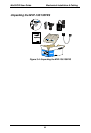
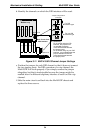
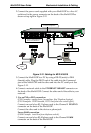
2. Connect the power cord supplied with your MultiVOIP to a live AC
outlet and to the power connector on the back of the MultiVOIP as
shown at top right in Figure 3-12.
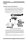
Ethernet Connection
Com m an d P or t C on n ec t ion
COMMA ND
10 BASET
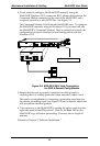
E& M FXS/FXO E&M FXS/FXO
E&M FXS /FXO E&M FXS/FXO
E&M
FXO
PSTN
E&M FXS/FXO
FXS
E& M FXS/FX O E &M FXS/FXO E&M FXS/FXO E&M FXS/FXO
Voice/Fax Channel Connections
Channels 1-4 Bottom MVP410/810
Channels 5-8 Top MVP810 Only
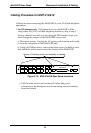
COMMA ND
MODEM
ETHE RNET
Command Modem connector
for remote configuration
Figure 3-12: Cabling for MVP-410/810
3. Connect the MultiVOIP to a PC by using a DB-25 (male) to DB-9
(female) cable. Plug the DB-25 end of the cable into the Command
port of the MultiVOIP and the other end into the PC serial port. See
Figure 3-12.
4. Connect a network cable to the ETHERNET 10BASET connector on
the back of the MultiVOIP. Connect the other end of the cable to your
network.
5. For an FXS or FXO connection.
(FXS Examples: analog phone, fax machine, Key Telephone System.)
(FXO Examples: PBX extension, POTS line from telco central office.)
Connect one end of an RJ-11 phone cord to the Channel 1 FXS/FXO
connector on the back of the MultiVOIP.
Connect the other end to the device or phone jack.
For an E&M connection.
(E&M Example: trunk line from telephone switch.)
Connect one end of an RJ-45 phone cord to the Channel 1 E&M
connector on the back of the MultiVOIP.