


Mechanical Installation & Cabling MultiVOIP User Guide
106
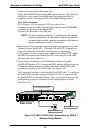
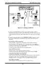
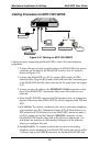
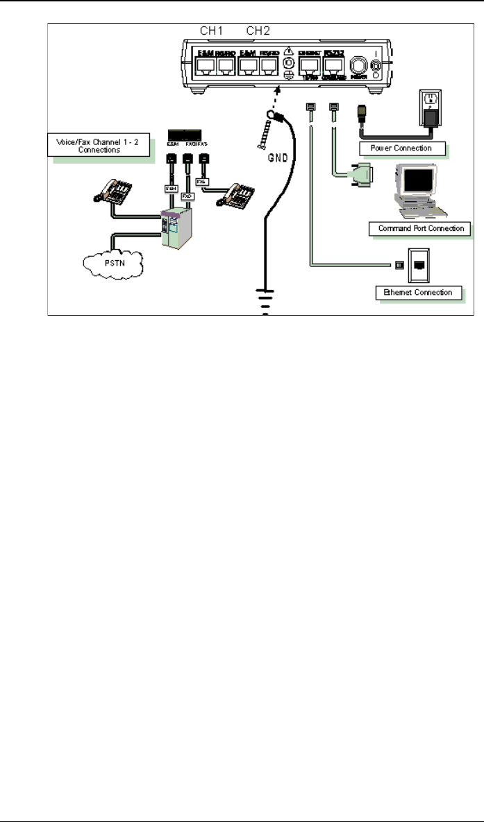
Figure 3-17: Cabling for MVP210
3. Connect the MultiVOIP to a PC by using a RJ-45 (male) to DB-9
(female) cable. Plug the RJ-45 end of the cable into the Command port
of the MultiVOIP and the other end into the PC serial port. See Figure
3-17.
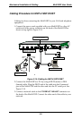
4. Connect a network cable to the ETHERNET 10/100 connector on the
back of the MultiVOIP. Connect the other end of the cable to your
network.
5. For an FXS or FXO connection.
(FXS Examples: analog phone, fax machine, Key Telephone System.)
(FXO Examples: PBX extension, POTS line from telco central office.)
Connect one end of an RJ-11 phone cord to the Channel 1 FXS/FXO
connector on the back of the MultiVOIP.
Connect the other end to the device or phone jack.
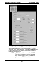
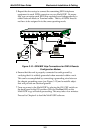
For an E&M connection.
(E&M Example: trunk line from telephone switch.)
Connect one end of an RJ-45 phone cord to the Channel 1 E&M
connector on the back of the MultiVOIP.
Connect the other end to the trunk line.
Verify that the E&M Type in the E&M Options group of the Interface
dialog box is the same as the E&M trunk type supported by the
telephone switch. See Appendix B for an E&M cabling pinout.
For a DID connection.
(DID Example: DID fax system or DID voice phone lines.)