


MultiVOIP User Guide Mechanical Installation & Cabling
93
Cabling
Cabling Procedure for MVP2410/3010
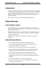
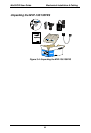
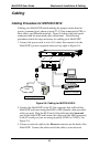
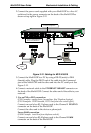
Cabling your MultiVOIP entails making the proper connections for
power, command port, phone system (T1/E1 line connected to PBX or
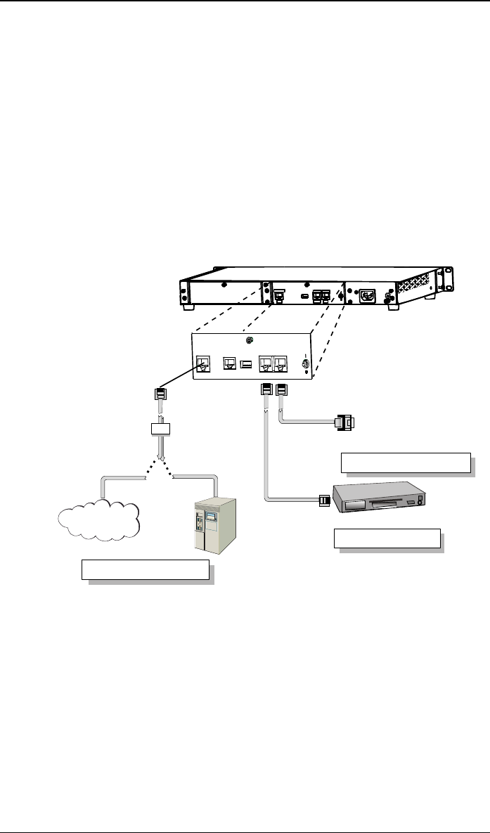
telco office), and Ethernet network. Figure 3-8 shows the back panel
connectors and the associated cable connections. The following
procedure details the steps necessary for cabling your MultiVOIP.
1. Connect the power cord to a live AC outlet, then connect it to the
MultiVOIP’s power receptacle shown at top right in Figure 3-8.
ETHERNET COMMAND
DIGITAL VOICE
ETHERNETCOMMAND
10 BASET
RS232
DIGITAL VOICE
TRUNK
T1
PBX
PSTN
Telephony Connection
Network Connection
Command Port Connection
COMMAND
MODEM
Hub
Figure 3-8. Cabling for MVP2410/3010
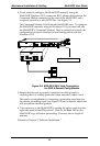
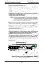
2. Connect the MultiVOIP to the PC (the computer that will hold the
MultiVOIP software) using the RJ-45 to DB9 (female) cable provided
with your unit. Plug the RJ-45 end of the cable into the Command
port of the MultiVOIP and connect the other end (the DB9 connector)
to the PC serial port you are using (typically COM1 or COM2). See
Figure 3-8.
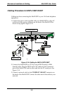
3. Connect a network cable to the Ethernet connector on the back of the
MultiVOIP. Connect the other end of the cable to your network.