


Mechanical Installation & Cabling MultiVOIP User Guide
96
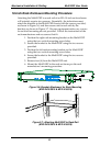
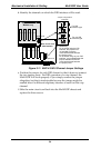
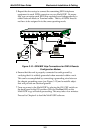
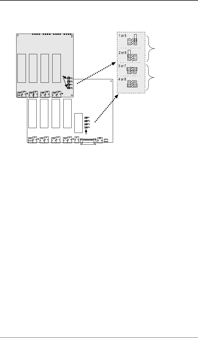
d. Identify the channels on which the DID interface will be used.
For DID
Interface type
For non-DID
Interface type
Ch 1
Ch 2
Ch 3
Ch 4
Jumpers 1-4
}
}
U9U7 U8
U10
Ch 5
Ch 6
Ch 7
Ch 8
Jumpers 5-8
Jumper Configurations
(enlarged)
MVP-410/810
MVP810 only
Generality:
For channels using the DID
interface, the jumper must
not
straddle across the
cross-hatched area between
the jumper posts.
For channels using any non-DID
interface, it is acceptable that the
jumper straddles across the
cross-hatched area between
the jumper posts.
Upper Circuit Card
Main Circuit Card
Figure 3-11. MVP-410/810 Channel Jumper Settings
e. Position the jumper for each DID channel so that it does not connect
the two jumper posts. For DID operation of a voip channel, the
MultiVOIP will work properly if you simply remove the jumper
altogether, but that is inadviseable because the jumper might be
needed later if a different telephony interface is used for that voip
channel.
f. Slide the main circuit card back into the MultiVOIP chassis and
replace the three screws.