


MultiVOIP User Guide Mechanical Installation & Cabling
95
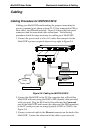
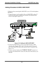
Cabling Procedure for MVP-410/810
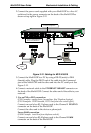
Cabling involves connecting the MultiVOIP to your LAN and telephone
equipment.
1.
For DID channels only. If all channels of your MultiVOIP will be
using either FXS, FXO, or E&M telephony interfaces, skip to step 2.
For any channel on which you are using the DID interface type, you
must change the jumper on the MultiVOIP circuit card.
a. Disconnect power. Unplug the AC power cord from the wall outlet
or from the receptacle on the MultiVOIP unit.
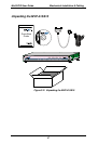
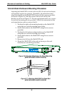
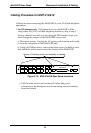
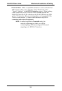
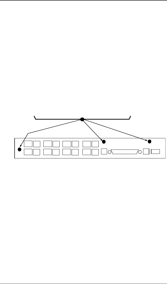
b. Using a #1 Phillips driver, remove the three screws (at back of unit)
that attach the main circuit card to the chassis of the MultiVOIP.
x
x
x
Screws (3) holding circuit card assembly to chassis.
MVP410/810
rear panel
Figure 3-10. MVP-410/810 Rear Screw Locations
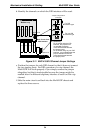
c. Pull the main circuit card out about 5 inches (the power
connection to the board prevents it from being removed entirely
from the chassis).