


Overview MultiVOIP User Guide
26
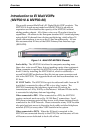
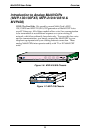
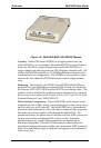
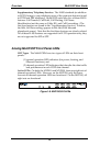
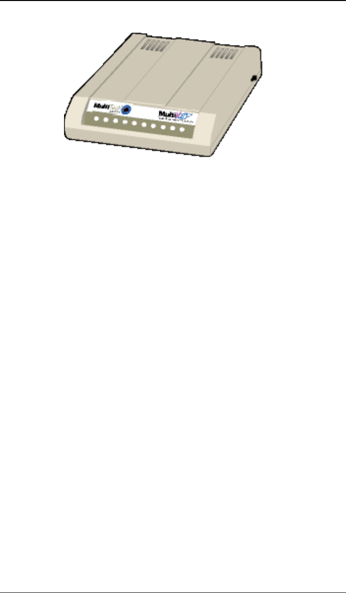
Figure 1-8: MultiVOIP MVP-130/130FXS Chassis
Capacity. MultiVOIP model MVP810 is an eight-channel unit, the
model MVP410 is a four-channel, the model MVP210 is a two-channel
units, the MV130 is a single-channel unit and the MVP130FXS is a
single-channel unit that supports the FXS telephony interface only. All
of these MultiVOIP units have a 10/100Mbps Ethernet interface and a
command port for configuration. The MVP428 is an expansion circuit
card for the four-channel MVP410 that turns it into an eight-channel
voip.
Mounting. Mechanically, the MVP410 and MVP810 MultiVOIPs are
designed for a one-high industry-standard EIA 19-inch rack enclosure.
By contrast, MVP-130/130FXS and the MVP210 are tabletop units. The
product must be installed by qualified service personnel in a restricted-
access area, in accordance with Articles 110-16, 10-17, and 110-18 of the
National Electrical Code, ANSI/NFPA 70.
Phone System Transparency. These MultiVOIPs inter-operate with a
telephone switch or PBX, acting as a switching device that directs voice
and fax calls over an IP network. The MultiVOIPs have “phonebooks,”
directories that determine to who calls may be made and the sequences
that must be used to complete calls through the MultiVOIP. The
phonebooks allow the phone user to interact with the VOIP system just
as they would with an ordinary PBX or telco switch. When the
phonebooks are set, special dialing sequences are minimized or
eliminated altogether. Once the call destination is determined, the
phonebook settings determine whether the destination VOIP unit must
strip off or add dialing digits to make the call appear at its destination
to be a local call.