


MultiVOIP User Guide Mechanical Installation & Cabling
103
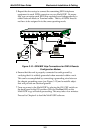
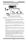
5. Repeat the above step to connect the remaining ISDN telephone
equipment to each ISDN connector on your MultiVOIP. Be aware
that you can assign each ISDN line separately and independently to
either Network mode or Terminal mode. That is, all ISDN lines do
not have to be assigned in to the same operating mode.
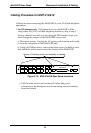
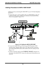
Ethernet Connection
Command Port Connection
COMMAND
ETHERNET
10 BASET
TERMINAL
MODE
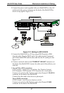
ISDN-B RI Con nections
I SDN1 & I SDN 2 : MV P41 0ST /8 10ST
ISDN3 & ISDN4: MVP810ST only
ISDN1 ISDN2 ISDN3 ISDN4
?
NETWORK
MO D E
IS D N
TA
PBX
PSTN
NT1
Device
*
* NT1 Device
is needed
if PBX has “U” interface.
Grounding Screw
Figure 3-15: ISDN/BRI Voip Connections for GND & Remote
Configuration Modem
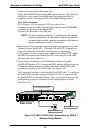
6. Ensure that the unit is properly connected to earth ground by
verifying that it is reliably grounded when mounted within a rack.
This can be accomplished by connecting a grounding wire between
the chassis grounding screw (see Figure 3-15) and a metallic object
that will provide an electrical ground.
7. Turn on power to the MultiVOIP by placing the ON/OFF switch on
the back panel to the ON position. Wait for the Boot LED on the
MultiVOIP to go off before proceeding. This may take a few minutes.
Proceed to Chapter 4 to load the MultiVOIP software.