


Mechanical Installation & Cabling MultiVOIP User Guide
108
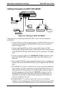
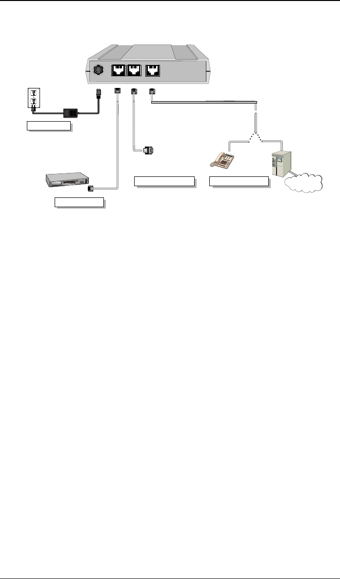
Cabling Procedure for MVP-130/130FXS
Power Connection
Network Connection
Ethernet
Command
Power
FXS/FXO
Command Port Connection
PBX
PSTN
Telephony Connection
FXS
FXO
Hub
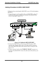
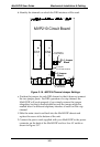
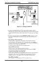
Figure 3-18: Cabling for MVP-130/130FXS
Cabling involves connecting the MultiVOIP to your LAN and telephone
equipment.
1. Connect the power cord supplied with your MultiVOIP to the power
connector on the back of the MultiVOIP and to a live AC outlet as
shown in Figure 3-18.
2. Connect the MultiVOIP to a PC by using a RJ-45 (male) to DB-9
(female) cable. Plug the RJ-45 end of the cable into the Command port
of the MultiVOIP and the other end into the PC serial port. See Figure
3-18.
3. Connect a network cable to the ETHERNET 10/100 connector on the
back of the MultiVOIP. Connect the other end of the cable to your
network.
4. Since the MVP130FXS supports the FXS interface only, its connection
options differ from that of the MVP130, which supports both FXS and
FXO.
A.
For MVP130. To connect a station device such as an analog telephone,
a fax machine, or a Key Telephone System (KTS) (FXS interface), or a
PBX extension (FXO interface) to your MultiVOIP, attach one end of
an RJ-11 phone cord to the Channel 1 FXS/FXO connector on the
back MultiVOIP and the other end to the device or phone jack. You
will define the interface in the Interface dialog box in the software
when you configure the unit.
B.
For MVP130FXS. To connect a station device such as an analog
telephone or fax machine to your MultiVOIP, attach one end of an RJ-
11 phone cord to the VOICE connector on the back MultiVOIP and