


SERVICING
4-5
February 2001
Part No. 001-9800-001
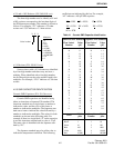
4.3.5 DETERMINING SYNTHESIZER COUNTER
DIVIDE NUMBERS
NOTE: For more information on the operation of the
counters in U801, refer to Section 3.7.5.
Overall Div No. (K) = VCO freq ÷ .050
Example: 813.4875 ÷ .050 = 16,269.75
“A” Divide No. = 64 x Fraction (Integer K ÷ 64)
Example: 16,269 ÷ 64 = 254.20312
Fraction 254.20312 = 0.20312
64 x 0.20312 = 13
“N” Divide No. = Integer [K ÷ 64] – A
Example: Integer 254.20312 = 254
254 – 13 = 241
Fractional-N Div No. = (Fraction K) x 8
Example: Fraction 16,269.75 = 0.75
0.75 x 8 = 6
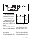
4.4 RECEIVER SERVICING
To isolate a receiver problem to a specific
section, check the DC and RF voltages shown on the
schematic diagram.
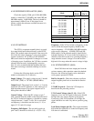
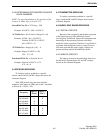
With UHF models only, the front end filter
frequency shift inputs on U800, pins 6 and 7 should be
as follows (L = 0V, H = 5V):
4.5 TRANSMITTER SERVICING
To isolate a transmitter problem to a specific
stage, check the DC and RF voltages shown on the
schematic diagram.
4.6 AUDIO/LOGIC BOARD SERVICING
4.6.1 DIGITAL CIRCUITS
Because of the complexity and dynamic operation
of the digital portion of the audio/logic board,
servicing may be difficult. Special test equipment and
knowledge of the operating software are usually
needed to isolate a problem. Therefore, if a problem is
suspected with the digital circuitry, it may be best to
first make sure that the proper supply voltages are
present and then replace the audio/logic board.
4.6.2 ANALOG CIRCUITS
The analog circuits on the audio/logic board can
be checked by measuring the AC and DC voltages
shown on the schematic diagram.
Frequency
Shift F1
(Pin 6)
Shift F2
(Pin 7)
430-440 MHz H H
440-450 MHz L H
450-460 MHz H L
460-470 MHz L L
470-480 MHz H H
480-491 MHz L H
491-502 MHz H L
502-512 MHz L L