


INSTALLATION
2-8
February 2001
Part No. 001-9800-001
2.7.1 GENERAL
The optional data pigtail cable is supported by
Multi-Net versions only. It is installed when a modem
or some other type of data device is to be connected to
the transceiver. This cable connects the data equip-
ment to data connector J301 on the audio/logic board.
Two data cables are available (see Table 1-3), and
descriptions of each follow.
Data/Accessory Pigtail Cable, Part No. 597-9800-001
This cable is a combination data and accessory
pigtail cable. It does not include a connector for inter-
facing with
the data equipment. The wires are untermi-
nated and connected to a user-supplied connector as
desired. The cable has 15 conductors. All 13 pins of
J301 are brought out, and there are two additional
wires that can be connected inside the transceiver as
desired.
Data Pigtail Cable, Part No. 597-9800-005
This is a data cable only (it does not include the
accessory cable). The data cable is similar to the one
included with the -001 cable. It has 15 unterminated
wires, and a user supplied connector is installed as
desired.
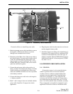
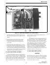
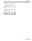
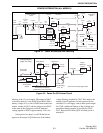
2.7.2 DATA CABLE INSTALLATION
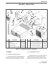
1. Remove the bottom cover of the transceiver to
access the audio/logic board.
2. Refer to Figure 2-6 and plug the 13-pin connector of
the data cable into J301. If also installing the acces-
sory cable, plug the 7-pin connector into J701. Refer
to Section 2.4 for more accessory cable installation
information.
3. Refer to the wiring chart in Table 2-1 and connect
the data cable wires to the user supplied connector
as required for the data equipment being used.
4. If required, install the purple and pink wires to the
desired points in the transceiver.
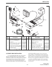
5. Position the strain relief grommet of the accessory/
data cable in the external speaker jack slot of the
chassis as shown in Figure 2-6 and reinstall the
bottom cover. bottom cover.
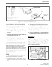
2.8 KEY CAP KITS
NOTE: To remove a key cap, insert a tool with a sharp
tip in the slot on the bottom of the cap and carefully
pry against the front panel to release the cap.
2.8.1 MULTI-NET AND LTR-NET MODELS
Key Cap Kit, Part No. 587-9840-001, is standard
with each Multi-Net transceiver and includes the five
caps indicated below.
FCN SCAN A/D TA AUX
Key Cap Kit, Part No. 587-9840-002, is standard
with each LTR-Net transceiver and includes the five
caps indicated by an asterisk (*) in the list which
follows.
An optional key cap kit, Part No. 587-9840-004,
is also available which includes all of the caps in the
following list:
FCN* SCAN* A/D* ROAM* TEL*
TA AUX HOME PAGE HORN
C/G PRI USR1 USR2 MON
CPND MHNG STLH MICPA BANK
EMER ENCPT Rx PA CALL
(Blank) (Blank)
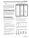
Table 2-1 Data Cable Wire Chart
J301 Pin No. Function Wire Color
1 Sw Bat Out White
2 Rx Filt Out Green
3 Tx Filt In Yellow
4 TxD Blue
5 RxD Orange
6TransmitGray
7IN2 Brown
8 Ext Serv Req White/Red
9 Option 1 White/Green
10 Output C White/Black
11 Ext Pwr Sw White/Blue
12 8V Out Red
13 Ground Black
NC User Defined Purple
NC User Defined Pink